
Homework Answers


Add Answer to:
Problem 1: Consider the following block diagrams: a. Find the system transfer function C(s)/R(S). Simplify as...
asap Problem 1) (25 Pts.) C(s) a) Simplify the below block diagram to find the overall...
 asap
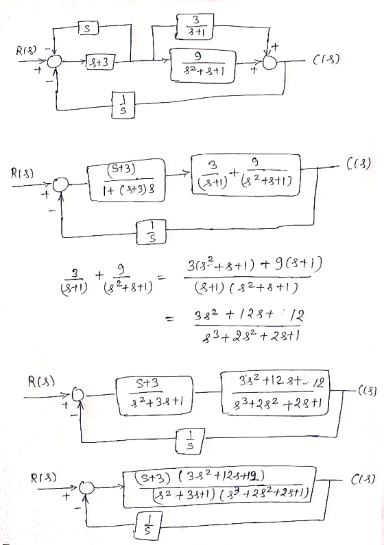
Problem 1) (25 Pts.) C(s) a) Simplify the below block diagram to find the overall system transfer function G(s)R Show your work including all intermediate block diagrams you may require. b) Given input r(t) is a unit step, find output time response c(t). (Hint: By MATLAB might be easiest).
asap
Problem 1) (25 Pts.) C(s) a) Simplify the below block diagram to find the overall system transfer function G(s)R Show your work including all intermediate block diagrams you may require. b) Given input r(t) is a unit step, find output time response c(t). (Hint: By MATLAB might be easiest).
4. Block Diagrams (a) Consider a causal LTI system with transfer function Show the direct-form block diagram of Hi(s) b) Consider a causal LTI system with transfer function H282+4s -6 H (s) = 2 Show...
 4. Block Diagrams (a) Consider a causal LTI system with transfer function Show the direct-form block diagram of Hi(s) b) Consider a causal LTI system with transfer function H282+4s -6 H (s) = 2 Show the direct-form block diagram of Hi(s) (c) Now observe that to draw a block diagram as a cascaded combination of two 1st order subsystems. (d) Finally, use partial fraction expansion to express this system as a sum of individual poles and observe that you can...
4. Block Diagrams (a) Consider a causal LTI system with transfer function H(s)2 Show the direct-form block diagram of Hi(s) (b) Consider a causal LTI system with transfer function 2s2 +4s -6 H(s)- Sh...
 4. Block Diagrams (a) Consider a causal LTI system with transfer function H(s)2 Show the direct-form block diagram of Hi(s) (b) Consider a causal LTI system with transfer function 2s2 +4s -6 H(s)- Show the direct-form block diagram of Hi(s) c) Now observe that to draw a block diagram as a cascaded combination of two 1st order subsystems. d) Finally, use partial fraction expansion to express this system as a sum of individual poles and observe that you can draw...
[HELP!] 1. Simplify the following block diagram. Obtain the transfer function from R to C for Fig. 1, and the transfer function from X(s) to Y(s) for Fig. 2. 2. Convert the block diagram of figures 1 and 2 to a signal flow graph.
 Simplify the following block diagram. Obtain the transfer function from R to C for Fig. 1,
and the transfer function from X(s) to Y(s) for Fig. 2.Convert the block diagram of figures 1 and 2 to a signal flow graph.Below are the diagrams:
Simplify the following block diagram. Obtain the transfer function from R to C for Fig. 1,
and the transfer function from X(s) to Y(s) for Fig. 2.Convert the block diagram of figures 1 and 2 to a signal flow graph.Below are the diagrams:
Consider the block diagram of the following control system. Find the transfer function G(s) = Y(S)/R(s)...
 Consider the block diagram of the following control system. Find the transfer function G(s) = Y(S)/R(s) by using the block diagram reduction R(5) Y(s) + 5+2 s
C(8) for the system shown in Figure 1. R(S Find the equivalent transfer function, Geg (s)...
 C(8) for the system shown in Figure 1. R(S Find the equivalent transfer function, Geg (s) 1 Cix) Figure 1. Block diagram 2s+1 s(5s+6Ge(s) = and Figure 2 shows a closed-loop transfer function, where G(s) 2. proper H(s) K+s. Find the overall closed-loop transfer function and express is as rational function. C(s) Ea (s) Controller R(s) +/ Plant G(s) Ge (s) Feedback H(s) Figure 2. Closed loop transfer function Construct the actuation Error Transfer Function associated with the system shown...
Section VI: Block Diagram Reduction Individually reduce each of the following Block Diagrams into a single...
 Section VI: Block Diagram Reduction Individually reduce each of the following Block Diagrams into a single block with a transfer function G(s) expressed as a ratio of two polynomials N(s) / D(s) CV(S) R(s) H1 SH3 2 4
PROBLEMS B-2-1. Simplify the block diagram shown in Figure 2-29 and obtain the closed-loop transfer function...
 PROBLEMS B-2-1. Simplify the block diagram shown in Figure 2-29 and obtain the closed-loop transfer function C(s)/RS). B-2-2. Simplify the block diagram shown in Figure 2-30 and obtain the closed-loop transfer function C(s)/R(s). B-2-3. Simplify the block diagram shown in Figure 2-31 and obtain the closed-loop transfer function C(s)/R(S). G1 R(S) CS) Figure 2-29 Block diagram of a system. Figure 2-30 Block diagram of a system. Figure 2-31 Block diagram of a system.
Simplify fractions as 2. Reduce the block diagrams below to find the equivalent transfer function G()...
 Simplify fractions as 2. Reduce the block diagrams below to find the equivalent transfer function G() = far as possible. (Part b Hint: Combine middle 2 summing junctions into one; Are all Loops and forward path touching? If so show a common element.) C. Cascade control: X(s) + Ga(s) 19 Gczs Gy(s) GP(s) >Y() HE(S) Hr(s) d. (Hint: Not touching.) 4 xe Q - 4 | : 6421 4 1 4G+ ] Y(S)
(i) Find the transfer function G(s) = Vo(s)/Vi(s) of this system using electrical impedances. Express the...
 (i) Find the transfer function G(s) = Vo(s)/Vi(s) of this system using electrical impedances. Express the transfer function as a ratio of two s polynomials. (ii) Plot the output voltage v, as a function of time by means of the transfer function determined at (i) for an input voltage vi= 120e0.18 Volt, R2 = 110 9, R2 = 900, R3 = 100 0, L = 3H and C= 80-106 F. Use MATLAB's step command to plot volt). Also use Simulink...
 asap
Problem 1) (25 Pts.) C(s) a) Simplify the below block diagram to find the overall system transfer function G(s)R Show your work including all intermediate block diagrams you may require. b) Given input r(t) is a unit step, find output time response c(t). (Hint: By MATLAB might be easiest).
asap
Problem 1) (25 Pts.) C(s) a) Simplify the below block diagram to find the overall system transfer function G(s)R Show your work including all intermediate block diagrams you may require. b) Given input r(t) is a unit step, find output time response c(t). (Hint: By MATLAB might be easiest).
 4. Block Diagrams (a) Consider a causal LTI system with transfer function Show the direct-form block diagram of Hi(s) b) Consider a causal LTI system with transfer function H282+4s -6 H (s) = 2 Show the direct-form block diagram of Hi(s) (c) Now observe that to draw a block diagram as a cascaded combination of two 1st order subsystems. (d) Finally, use partial fraction expansion to express this system as a sum of individual poles and observe that you can...
 4. Block Diagrams (a) Consider a causal LTI system with transfer function H(s)2 Show the direct-form block diagram of Hi(s) (b) Consider a causal LTI system with transfer function 2s2 +4s -6 H(s)- Show the direct-form block diagram of Hi(s) c) Now observe that to draw a block diagram as a cascaded combination of two 1st order subsystems. d) Finally, use partial fraction expansion to express this system as a sum of individual poles and observe that you can draw...
 Consider the block diagram of the following control system. Find the transfer function G(s) = Y(S)/R(s) by using the block diagram reduction R(5) Y(s) + 5+2 s
 C(8) for the system shown in Figure 1. R(S Find the equivalent transfer function, Geg (s) 1 Cix) Figure 1. Block diagram 2s+1 s(5s+6Ge(s) = and Figure 2 shows a closed-loop transfer function, where G(s) 2. proper H(s) K+s. Find the overall closed-loop transfer function and express is as rational function. C(s) Ea (s) Controller R(s) +/ Plant G(s) Ge (s) Feedback H(s) Figure 2. Closed loop transfer function Construct the actuation Error Transfer Function associated with the system shown...
 Section VI: Block Diagram Reduction Individually reduce each of the following Block Diagrams into a single block with a transfer function G(s) expressed as a ratio of two polynomials N(s) / D(s) CV(S) R(s) H1 SH3 2 4
 PROBLEMS B-2-1. Simplify the block diagram shown in Figure 2-29 and obtain the closed-loop transfer function C(s)/RS). B-2-2. Simplify the block diagram shown in Figure 2-30 and obtain the closed-loop transfer function C(s)/R(s). B-2-3. Simplify the block diagram shown in Figure 2-31 and obtain the closed-loop transfer function C(s)/R(S). G1 R(S) CS) Figure 2-29 Block diagram of a system. Figure 2-30 Block diagram of a system. Figure 2-31 Block diagram of a system.
 Simplify fractions as 2. Reduce the block diagrams below to find the equivalent transfer function G() = far as possible. (Part b Hint: Combine middle 2 summing junctions into one; Are all Loops and forward path touching? If so show a common element.) C. Cascade control: X(s) + Ga(s) 19 Gczs Gy(s) GP(s) >Y() HE(S) Hr(s) d. (Hint: Not touching.) 4 xe Q - 4 | : 6421 4 1 4G+ ] Y(S)
 (i) Find the transfer function G(s) = Vo(s)/Vi(s) of this system using electrical impedances. Express the transfer function as a ratio of two s polynomials. (ii) Plot the output voltage v, as a function of time by means of the transfer function determined at (i) for an input voltage vi= 120e0.18 Volt, R2 = 110 9, R2 = 900, R3 = 100 0, L = 3H and C= 80-106 F. Use MATLAB's step command to plot volt). Also use Simulink...
Most questions answered within 3 hours.
-
91. If the half – life of a sample of radioactive
material is 60 days, what...
asked 35 seconds from now -
White light (380nm-750nm) strikes a diffraction grating (420
lines/mm) at normal incidence. What is the highest-order...
asked 9 minutes ago -
1) Explain what is meant by a good being "excludable."?
2) Explain what is meant by...
asked 8 minutes ago -
I need help with this question:
Describe in detail at least two factors that stimulated American...
asked 15 minutes ago -
Calculate the Boyle temperature for helium assuming it follows
the Berthelot equation of state.
asked 16 minutes ago -
Summarize Strategic Corporate Social Responsibility, 4th edition
2017 book, chapter one and two.
asked 16 minutes ago -
1. If the standard deviations for return on stock A and stock B
are 28% and...
asked 31 minutes ago -
Please use python to explain.
Assume that the variables x and
y refer to strings. Write...
asked 38 minutes ago -
This table shows the US domestic demand and supply schedules
for oranges. Suppose the world price...
asked 37 minutes ago -
Please help me create a CLASS DIAGRAM for this code:
import pygame
from pygame.sprite import Sprite...
asked 39 minutes ago -
The Merriweather Printing Company is trying to decide on the
merits of constructing a new publishing...
asked 58 minutes ago -
29) Insulin is a water-soluble hormone transported in the blood.
Which describes a likely way in...
asked 1 hour ago