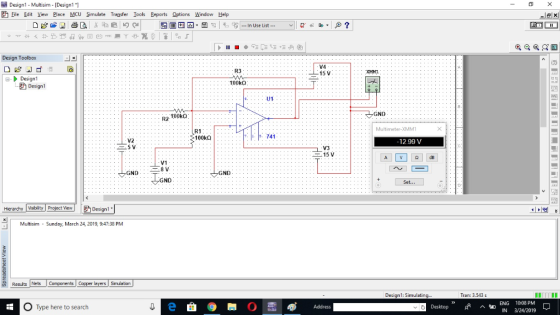
Design the circuit below using Multisim:
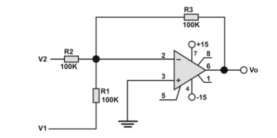
Then adjust value of V1 and V2 from table below to find Vo:

Please help me with this problem, thank you
Homework Answers


Add Answer to:
Design the circuit below using Multisim:
Then adjust value of V1 and V2 from table below...
a) Use MultiSim to find Vo in the circuit below. Paste your Multisim circuit showing the value of Vo in the space below...
 a) Use MultiSim to find Vo in the circuit below. Paste your
Multisim circuit showing the value of Vo in the space below.
b) Use mesh analysis to solve the same problem by hand. Show
your work in the space below. Compare the Multisim answer to that
obtained by hand. Are they the same?
5 A 2Ω 20 V 412 40 V (+ V: 27.1 V V(PP): 2.07 pv V(rms): 0Vv V(dc): 27.1V V(freq): 5A R2 R3 PR1 R1 2Ω...
a) Use MultiSim to find Vo in the circuit below. Paste your
Multisim circuit showing the value of Vo in the space below.
b) Use mesh analysis to solve the same problem by hand. Show
your work in the space below. Compare the Multisim answer to that
obtained by hand. Are they the same?
5 A 2Ω 20 V 412 40 V (+ V: 27.1 V V(PP): 2.07 pv V(rms): 0Vv V(dc): 27.1V V(freq): 5A R2 R3 PR1 R1 2Ω...
B- Multisim Simulations: a) Create a Multisim circuit (similar to Fig.1) with the followings: 10 1....
 B- Multisim Simulations: a) Create a Multisim circuit (similar to Fig.1) with the followings: 10 1. One Voltmeter measures the source voltage E and 3 Voltmeters measure V1, V2, V3. 2. Three Ammeters measure source current at A, B and C. Figure 1: Is A V1 + M R1 47002 + R2 } 5 V 62003 R3 1k02 | V3 + C
For the circuit below, determine the MAGNITUDE of the CURRENT passing through each resistor. V1 =...
 For the circuit below, determine the MAGNITUDE of the
CURRENT passing through each resistor. V1 = 7 V,
V2 = 12 V, V3 = 4 V, R1 = 19 Ω,
R2 = 3 Ω, R3 = 6 Ω.
For the circuit below, determine the MAGNITUDE of the CURRENT passing through each resistor. V1-7 V, V2 = 12 V, V3 = 4 V, R1 = 19 Ω, R2-3 Ω, R3 = 6 Ω. R1 V I3-
For the circuit below, determine the MAGNITUDE of the
CURRENT passing through each resistor. V1 = 7 V,
V2 = 12 V, V3 = 4 V, R1 = 19 Ω,
R2 = 3 Ω, R3 = 6 Ω.
For the circuit below, determine the MAGNITUDE of the CURRENT passing through each resistor. V1-7 V, V2 = 12 V, V3 = 4 V, R1 = 19 Ω, R2-3 Ω, R3 = 6 Ω. R1 V I3-
Assuming an ideal op-amp in the following circuit, find output voltage, Vo if R1= 2 K2,...
 Assuming an ideal op-amp in the following circuit, find output voltage, Vo if R1= 2 K2, R2=8 K12, R3=3.8 KS2, R4=6 KI2, R5=15 KS2, R6=3.8 KN, RL=9.8 K12, V1=1V, 12=0.5 mA and V3=2.2 V. } R6 R1 w R5 w + Vo + } RL 12 R2 V1 R3 R4 + +1 V3 Using the above circuit, but consider the following component values: R1= 2 KN R2=8 K2, R3=4.1 K12, R4=6 KI2, R5=17.0 K12, R6=15 KI, RL=10 KI, V1=1V, 12=0.5mA...
6. Design the circuit below for A.-10(V2-Vi). Show work. VT OPAMP R4. ОРАМ Vo R2 R3...
 6. Design the circuit below for A.-10(V2-Vi). Show work. VT OPAMP R4. ОРАМ Vo R2 R3 R4 ОРАМ V2
For the circuit shown in the figure, If R1=512, R2=10N, R3=3N, V1= V1}V, V2=5V and V3=7V....
 For the circuit shown in the figure, If R1=512, R2=10N, R3=3N, V1= V1}V, V2=5V and V3=7V. What is the value of the current 11 (in A)? R1 -W R3 M + + V2 V. 3 R2 $ 12 13
Assuming an ideal op-amp in the following circuit, find output voltage, Vo if R1= 2 K2,...
 Assuming an ideal op-amp in the following circuit, find output voltage, Vo if R1= 2 K2, R2=8 K2, R3=5.1 K2, R4=6 KN, R5=14 KN, R6=4.2 KS, RL=10.3 KS, V1=1V, 12=0.5 mA and V3=3.2 V. R6 R1 R5 Vo w + * RL + 12 R2 V1 R3 R4 V3 Answer: OV Using the above circuit, but consider the following component values: R1= 2 K12 R2=8 K2, R3=2.9 K2, R4=6 KI2, R5=10.8 K92, R6=15 KO, RL=10 K2, V1=1V, 12=0.5mA and V3=2V....
Assuming an ideal op-amp in the following circuit, find output voltage, Vo if R1= 2 K12,...
 Assuming an ideal op-amp in the following circuit, find output voltage, Vo if R1= 2 K12, R2=8 KN, R3=3.9 KN, R4=6 KN, R5=18 K2, R6=4.4 KN, RL=12.5 KN, V1=1V, 12=0.5 mA and V3=3.4 V. R6 R1 R5 Vo + + RL R2 V1 R3 R4 + V3 Answer: LOV Using the above circuit, but consider the following component values: R1= 2 KO2 R2=8 K12, R3=3.6 K12, R4=6 K12, R5=16.9 KN, R6=15 KN, RL=10 KO, V1=1V, 12=0.5mA and V3=2V. What is...
Design the below operational amplifier circuit having one output, Vout, and two inputs, V1 and V2....
 Design the below operational amplifier circuit having one output, Vout, and two inputs, V1 and V2. The output must be related to the inputs by Vout = 2 V1 - 9 V2 26 km 180 kn 180 kn Rik - R2 kn Determine the value of R1 and Rz. R2 = ko R2 =
QUESTION 1 In the diode circuit shown aside, given that V1 = V2 = 2.7 V,...
 QUESTION 1 In the diode circuit shown aside, given that V1 = V2 = 2.7 V, R = 1 k12 R2 = 2 kn, R3 = 4k and assuming constant-voltage-drop diode model (Vo = 0.7 V), determine the voltage drop (V) across the resistor R1, if the switch (S) is connected to a. Position 1 b. Position 2 V = Na V2
 a) Use MultiSim to find Vo in the circuit below. Paste your
Multisim circuit showing the value of Vo in the space below.
b) Use mesh analysis to solve the same problem by hand. Show
your work in the space below. Compare the Multisim answer to that
obtained by hand. Are they the same?
5 A 2Ω 20 V 412 40 V (+ V: 27.1 V V(PP): 2.07 pv V(rms): 0Vv V(dc): 27.1V V(freq): 5A R2 R3 PR1 R1 2Ω...
a) Use MultiSim to find Vo in the circuit below. Paste your
Multisim circuit showing the value of Vo in the space below.
b) Use mesh analysis to solve the same problem by hand. Show
your work in the space below. Compare the Multisim answer to that
obtained by hand. Are they the same?
5 A 2Ω 20 V 412 40 V (+ V: 27.1 V V(PP): 2.07 pv V(rms): 0Vv V(dc): 27.1V V(freq): 5A R2 R3 PR1 R1 2Ω...
 B- Multisim Simulations: a) Create a Multisim circuit (similar to Fig.1) with the followings: 10 1. One Voltmeter measures the source voltage E and 3 Voltmeters measure V1, V2, V3. 2. Three Ammeters measure source current at A, B and C. Figure 1: Is A V1 + M R1 47002 + R2 } 5 V 62003 R3 1k02 | V3 + C
 For the circuit below, determine the MAGNITUDE of the
CURRENT passing through each resistor. V1 = 7 V,
V2 = 12 V, V3 = 4 V, R1 = 19 Ω,
R2 = 3 Ω, R3 = 6 Ω.
For the circuit below, determine the MAGNITUDE of the CURRENT passing through each resistor. V1-7 V, V2 = 12 V, V3 = 4 V, R1 = 19 Ω, R2-3 Ω, R3 = 6 Ω. R1 V I3-
For the circuit below, determine the MAGNITUDE of the
CURRENT passing through each resistor. V1 = 7 V,
V2 = 12 V, V3 = 4 V, R1 = 19 Ω,
R2 = 3 Ω, R3 = 6 Ω.
For the circuit below, determine the MAGNITUDE of the CURRENT passing through each resistor. V1-7 V, V2 = 12 V, V3 = 4 V, R1 = 19 Ω, R2-3 Ω, R3 = 6 Ω. R1 V I3-
 Assuming an ideal op-amp in the following circuit, find output voltage, Vo if R1= 2 K2, R2=8 K12, R3=3.8 KS2, R4=6 KI2, R5=15 KS2, R6=3.8 KN, RL=9.8 K12, V1=1V, 12=0.5 mA and V3=2.2 V. } R6 R1 w R5 w + Vo + } RL 12 R2 V1 R3 R4 + +1 V3 Using the above circuit, but consider the following component values: R1= 2 KN R2=8 K2, R3=4.1 K12, R4=6 KI2, R5=17.0 K12, R6=15 KI, RL=10 KI, V1=1V, 12=0.5mA...
 6. Design the circuit below for A.-10(V2-Vi). Show work. VT OPAMP R4. ОРАМ Vo R2 R3 R4 ОРАМ V2
 For the circuit shown in the figure, If R1=512, R2=10N, R3=3N, V1= V1}V, V2=5V and V3=7V. What is the value of the current 11 (in A)? R1 -W R3 M + + V2 V. 3 R2 $ 12 13
 Assuming an ideal op-amp in the following circuit, find output voltage, Vo if R1= 2 K2, R2=8 K2, R3=5.1 K2, R4=6 KN, R5=14 KN, R6=4.2 KS, RL=10.3 KS, V1=1V, 12=0.5 mA and V3=3.2 V. R6 R1 R5 Vo w + * RL + 12 R2 V1 R3 R4 V3 Answer: OV Using the above circuit, but consider the following component values: R1= 2 K12 R2=8 K2, R3=2.9 K2, R4=6 KI2, R5=10.8 K92, R6=15 KO, RL=10 K2, V1=1V, 12=0.5mA and V3=2V....
 Assuming an ideal op-amp in the following circuit, find output voltage, Vo if R1= 2 K12, R2=8 KN, R3=3.9 KN, R4=6 KN, R5=18 K2, R6=4.4 KN, RL=12.5 KN, V1=1V, 12=0.5 mA and V3=3.4 V. R6 R1 R5 Vo + + RL R2 V1 R3 R4 + V3 Answer: LOV Using the above circuit, but consider the following component values: R1= 2 KO2 R2=8 K12, R3=3.6 K12, R4=6 K12, R5=16.9 KN, R6=15 KN, RL=10 KO, V1=1V, 12=0.5mA and V3=2V. What is...
 Design the below operational amplifier circuit having one output, Vout, and two inputs, V1 and V2. The output must be related to the inputs by Vout = 2 V1 - 9 V2 26 km 180 kn 180 kn Rik - R2 kn Determine the value of R1 and Rz. R2 = ko R2 =
 QUESTION 1 In the diode circuit shown aside, given that V1 = V2 = 2.7 V, R = 1 k12 R2 = 2 kn, R3 = 4k and assuming constant-voltage-drop diode model (Vo = 0.7 V), determine the voltage drop (V) across the resistor R1, if the switch (S) is connected to a. Position 1 b. Position 2 V = Na V2
Most questions answered within 3 hours.
-
How does a linear regression allow you to better estimate
trends, costs, and other factors in...
asked 6 minutes ago -
1. (15%) Describe the difference between a pull (Kanban), push
and CONWIP production systems.
asked 2 minutes ago -
QUESTION 5
The total area under the Z distribution curve is equal to:
a.
10
b....
asked 11 minutes ago -
Using Python
The variables x and y refer to numbers. Write a code segment
that prompts...
asked 26 minutes ago -
If
the coefficient of static friction between a box and the floor is
0.35 with what...
asked 28 minutes ago -
A die is designed to punch holes with a radius of 1.08 10-2 m in
a...
asked 33 minutes ago -
government can increase import through
a. export subsidies
b. tax breaks
c. increase import tax
d....
asked 33 minutes ago -
Draw the following in the proper skeletal structure or line
angle formula.
5,6,6-tribromo-3,8-dicyclopropyl-7-isopentyldodecane
asked 38 minutes ago -
Two blocks of masses m1 and m2 hang at the ends of a string that
passes...
asked 39 minutes ago -
Linear programming is an excellent technique yet is not applied
nearly enough in the “real world.”...
asked 48 minutes ago -
What three alkenes yield 3-methylpentane on catalytic
hydrogenation?
asked 48 minutes ago -
In JAVA Create a program with an array with the following
data:
50 12 31 76...
asked 50 minutes ago