
Homework Answers
Firstly, the question is purely based on circuit theory. Here the key concept is to know the thevenin theorem.
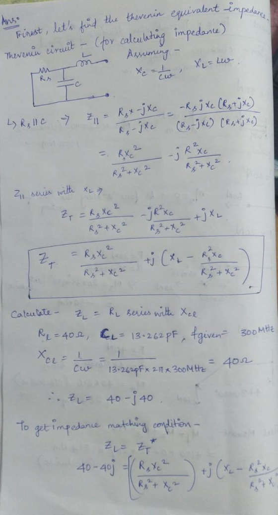
To find the thevenin circuit - remove the load ie R = 40 ohm and C = 13.262 pF. Next short the input voltage source.
Then find the equivalent impedance across the load terminals,
which will give
Then for impedance matching -
Refer below image for solution -

2. To calculate maximum power transferred
Formula -
But in this question, Vs ie input source voltage value is not given.
I will explain how to solve if provided.
While finding thevenin equivalent circuit, Vth should also be calculated. It is Voltage across the load terminals. Find Vth.
Use the above formula to calculate maximum power transferred
Add Answer to:
2. In the circuit shown below, the operating frequency for the transmit antenna is 300 MHz....
You have an antenna with an input impedance of Z (140 -j35)2 at f 120 MHz....
 You have an antenna with an input impedance of Z (140 -j35)2 at f 120 MHz. You would like to match this load to a 70Ω transmission line using a single stub tuner (vp-2.2x10⁸ m/s). Using the Smith chart, determine the distance d away from the load and the length l of a short-circuited parallel stub to accomplish the matching goal at the design frequency. Estimate the reduction in radiated power if the operating frequency is changed to f 125...
You are on an interview with Sungsam LTE and the interviewer shows you their new 2300 MHz cell phone transceiver and antenna printed circuit board (PCB) shown below. "Between the RF source an...
 You are on an interview with Sungsam LTE and the interviewer shows you their new 2300 MHz cell phone transceiver and antenna printed circuit board (PCB) shown below. "Between the RF source and antenna is a matching network of small circuit elements (i.e. inductor, capacitor or resistor) - the antenna feedline has a characteristic impedance Zo of 50 Ohms", she exclaims. She goes on to request you show her using her Smith Chart how you would 'match' the PCB trance...
Problem 10.22 Consider the transmission line shown, with series impedance ZL. negligible shunt admittance, and a...
 Problem 10.22 Consider the transmission line shown, with series impedance ZL. negligible shunt admittance, and a load impedance ZR at the receiving end. (a) Determine Zr for the given conditions of VR=1.0 per unit and SR - 2+0.8 per unit. (6) Construct the impedance diagram in the R-X plane for ZL -0.1+0.3 per unit. (c) Find Zs for this condition and the angle 8 between Zs and ZR. FIGURE 10.48 Vs Z Problem 10.22 Load
8.16 Using matching network shown below, find the stub length ls the characteristic impedance Zou...
 8.16 Using matching network shown below, find the stub length ls the characteristic impedance Zou and the transmission line length 11 such that the ZL = (80-j40) Ω load impedance is matched to a 50 Ω source. Assume that the characteristic impedance of the stubs Zos = 50 Ω. Zas ls Zin Open or short circuit
8.16 Using matching network shown below, find the stub length ls the characteristic impedance Zou and the transmission line length 11 such that the...
8.16 Using matching network shown below, find the stub length ls the characteristic impedance Zou and the transmission line length 11 such that the ZL = (80-j40) Ω load impedance is matched to a 50 Ω source. Assume that the characteristic impedance of the stubs Zos = 50 Ω. Zas ls Zin Open or short circuit
8.16 Using matching network shown below, find the stub length ls the characteristic impedance Zou and the transmission line length 11 such that the...
6. Design two single-stub matching networks as shown below. Transform the load impedance Z (60 j45) Ω to match an input impedance of Z,-(75+j90)Ω. Assume that both the stub and the transmission line...
 6. Design two single-stub matching networks as shown below. Transform the load impedance Z (60 j45) Ω to match an input impedance of Z,-(75+j90)Ω. Assume that both the stub and the transmission line shown below have a characteristic impedance of Zo-50 Ω. Zot I ZoL.l ZL lm in Open or -) : short circuit , open or short circuit
6. Design two single-stub matching networks as shown below. Transform the load impedance Z (60 j45) Ω to match an input...
6. Design two single-stub matching networks as shown below. Transform the load impedance Z (60 j45) Ω to match an input impedance of Z,-(75+j90)Ω. Assume that both the stub and the transmission line shown below have a characteristic impedance of Zo-50 Ω. Zot I ZoL.l ZL lm in Open or -) : short circuit , open or short circuit
6. Design two single-stub matching networks as shown below. Transform the load impedance Z (60 j45) Ω to match an input...
You are on an interview with Sungsam LTE and the interviewer shows you their new 2300 MHz cell ph...
 You are on an interview with Sungsam LTE and the interviewer shows you their new 2300 MHz cell phone transceiver and antenna printed circuit board (PCB) shown below. "Between the RF source and antenna is a matching network of small circuit elements (i.e. inductor, capacitor or resistor) - the antenna feedline has a characteristic impedance Zo of 50 Ohms", she exclaims. She goes on to request you show her using her Smith Chart how you would 'match the PCB trance...
In a radio frequency circuit, a resistance of 1752 Ω serves as a load at the...
In a radio frequency circuit, a resistance of 1752 Ω serves as a load at the end of a 50 Ω transmission line. We wish to connect an inductor, L, in series to the input of the line so that a source with an output impedance of 50 Ω does not see reflections. No need to know the frequency to solve the problem (a) Determine the minimum length of the transmission line in terms of wavelengths. (b) Determine the value...
1) A Hertzian dipole antenna is a short conducting wire carrying an approximately constant current over its length...
 1) A Hertzian dipole antenna is a short conducting wire carrying an approximately constant current over its length If such a dipole is placed along the z-axis with its midpoint at the origin, and if the current flowing through it is i(t) ż lo cosot, assume I to be sufficiently small so that the observation point is approximately equidistant to all points on the dipole; that is, assume RR then the corresponding magnetic field is described by: olk2 sin e...
Problem 3. The circuit, shown below, is composed of four transmission lines, T1, T2, T3, and...
 Problem 3. The circuit, shown below, is composed of four transmission lines, T1, T2, T3, and T4. Load impedance connected to the line T3 includes the resistor R1- 100 ohms and the parallel capacitor C1-30 pF. Determine the lengths of the transmission lines T2 (11) and T4 with open end (1 2) to match the impedance observed from the output terminals of the transmission line of TI (point A) to 50 ohms. The frequency, f-100 MHz. Assume air dielectric of...
answer number 3 and 4 Problem 7. Transmission Lines The figure below shows a transmission line with a characteristic impedance Z,-50 Ω, connected to a single frequency generator with an internal i...
 answer number 3 and 4
Problem 7. Transmission Lines The figure below shows a transmission line with a characteristic impedance Z,-50 Ω, connected to a single frequency generator with an internal impedance R,-50 C (not shown), and terminated in a purely resistive load RL 50 2. At the frequency of the generator, the wavelength of the transmission line is λ = 2 m. At a distance dl-1.25 m away from the load, a shorted stub is connected via a tee....
answer number 3 and 4
Problem 7. Transmission Lines The figure below shows a transmission line with a characteristic impedance Z,-50 Ω, connected to a single frequency generator with an internal impedance R,-50 C (not shown), and terminated in a purely resistive load RL 50 2. At the frequency of the generator, the wavelength of the transmission line is λ = 2 m. At a distance dl-1.25 m away from the load, a shorted stub is connected via a tee....
 You have an antenna with an input impedance of Z (140 -j35)2 at f 120 MHz. You would like to match this load to a 70Ω transmission line using a single stub tuner (vp-2.2x10⁸ m/s). Using the Smith chart, determine the distance d away from the load and the length l of a short-circuited parallel stub to accomplish the matching goal at the design frequency. Estimate the reduction in radiated power if the operating frequency is changed to f 125...
 You are on an interview with Sungsam LTE and the interviewer shows you their new 2300 MHz cell phone transceiver and antenna printed circuit board (PCB) shown below. "Between the RF source and antenna is a matching network of small circuit elements (i.e. inductor, capacitor or resistor) - the antenna feedline has a characteristic impedance Zo of 50 Ohms", she exclaims. She goes on to request you show her using her Smith Chart how you would 'match' the PCB trance...
 Problem 10.22 Consider the transmission line shown, with series impedance ZL. negligible shunt admittance, and a load impedance ZR at the receiving end. (a) Determine Zr for the given conditions of VR=1.0 per unit and SR - 2+0.8 per unit. (6) Construct the impedance diagram in the R-X plane for ZL -0.1+0.3 per unit. (c) Find Zs for this condition and the angle 8 between Zs and ZR. FIGURE 10.48 Vs Z Problem 10.22 Load
 8.16 Using matching network shown below, find the stub length ls the characteristic impedance Zou and the transmission line length 11 such that the ZL = (80-j40) Ω load impedance is matched to a 50 Ω source. Assume that the characteristic impedance of the stubs Zos = 50 Ω. Zas ls Zin Open or short circuit
8.16 Using matching network shown below, find the stub length ls the characteristic impedance Zou and the transmission line length 11 such that the...
8.16 Using matching network shown below, find the stub length ls the characteristic impedance Zou and the transmission line length 11 such that the ZL = (80-j40) Ω load impedance is matched to a 50 Ω source. Assume that the characteristic impedance of the stubs Zos = 50 Ω. Zas ls Zin Open or short circuit
8.16 Using matching network shown below, find the stub length ls the characteristic impedance Zou and the transmission line length 11 such that the...
 6. Design two single-stub matching networks as shown below. Transform the load impedance Z (60 j45) Ω to match an input impedance of Z,-(75+j90)Ω. Assume that both the stub and the transmission line shown below have a characteristic impedance of Zo-50 Ω. Zot I ZoL.l ZL lm in Open or -) : short circuit , open or short circuit
6. Design two single-stub matching networks as shown below. Transform the load impedance Z (60 j45) Ω to match an input...
6. Design two single-stub matching networks as shown below. Transform the load impedance Z (60 j45) Ω to match an input impedance of Z,-(75+j90)Ω. Assume that both the stub and the transmission line shown below have a characteristic impedance of Zo-50 Ω. Zot I ZoL.l ZL lm in Open or -) : short circuit , open or short circuit
6. Design two single-stub matching networks as shown below. Transform the load impedance Z (60 j45) Ω to match an input...
 You are on an interview with Sungsam LTE and the interviewer shows you their new 2300 MHz cell phone transceiver and antenna printed circuit board (PCB) shown below. "Between the RF source and antenna is a matching network of small circuit elements (i.e. inductor, capacitor or resistor) - the antenna feedline has a characteristic impedance Zo of 50 Ohms", she exclaims. She goes on to request you show her using her Smith Chart how you would 'match the PCB trance...
 1) A Hertzian dipole antenna is a short conducting wire carrying an approximately constant current over its length If such a dipole is placed along the z-axis with its midpoint at the origin, and if the current flowing through it is i(t) ż lo cosot, assume I to be sufficiently small so that the observation point is approximately equidistant to all points on the dipole; that is, assume RR then the corresponding magnetic field is described by: olk2 sin e...
 Problem 3. The circuit, shown below, is composed of four transmission lines, T1, T2, T3, and T4. Load impedance connected to the line T3 includes the resistor R1- 100 ohms and the parallel capacitor C1-30 pF. Determine the lengths of the transmission lines T2 (11) and T4 with open end (1 2) to match the impedance observed from the output terminals of the transmission line of TI (point A) to 50 ohms. The frequency, f-100 MHz. Assume air dielectric of...
 answer number 3 and 4
Problem 7. Transmission Lines The figure below shows a transmission line with a characteristic impedance Z,-50 Ω, connected to a single frequency generator with an internal impedance R,-50 C (not shown), and terminated in a purely resistive load RL 50 2. At the frequency of the generator, the wavelength of the transmission line is λ = 2 m. At a distance dl-1.25 m away from the load, a shorted stub is connected via a tee....
answer number 3 and 4
Problem 7. Transmission Lines The figure below shows a transmission line with a characteristic impedance Z,-50 Ω, connected to a single frequency generator with an internal impedance R,-50 C (not shown), and terminated in a purely resistive load RL 50 2. At the frequency of the generator, the wavelength of the transmission line is λ = 2 m. At a distance dl-1.25 m away from the load, a shorted stub is connected via a tee....
Most questions answered within 3 hours.
-
R2.84: There are 2 defective products in a production lot of 10.
An inspector randomly selected...
asked 4 minutes ago -
Consider the following equilibrium system: COCl2(g) CO(g) +
Cl2(g) A 10.00 L evacuated flask is filled...
asked 32 minutes ago -
1) What are the two distinct steps that one needs to perform
when developing a data...
asked 36 minutes ago -
2) Write a C++ program that uses a class called “Degree” to
obtain the trigonometric
values...
asked 1 hour ago -
1. In eukaryotic cells the genomes of
&
asked 1 hour ago -
The standard enthalpy of propanol (C3H7OH) is -303.0 kJ/mol.
Compute both of the
gross and net...
asked 1 hour ago -
Why PWM using H-bridge for control motor speed is more power
effiecient than the linear amplifier...
asked 1 hour ago -
In 1999, Carly Fiorina famously said,"I hope that we are at a
point that everyone is...
asked 1 hour ago -
Individuals in a species of moth vary in wing color from white to
black, but all...
asked 2 hours ago -
The following standards for variable manufacturing overhead have
been established for a company that makes only...
asked 2 hours ago -
The United States government wanted to determine what proportion
of Americans approve of the current president,...
asked 2 hours ago -
2-N stone is dropped from the top of a cliff. The stone hits the
ground 3...
asked 2 hours ago