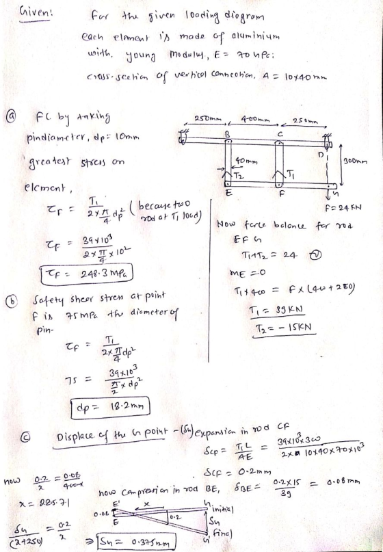
In the system, each element is made of aluminum.
and E = 70 GPa. Cross sections of vertical connections 10x40
Mm. For the upload shown
a) FC by taking pin diameters 10 mm only for this option
the greatest stress in the element.
b) Safety shear stress at point F for 75 MPa
the diameter of the pin,
c) Displacement of the G point,
You calculate.

Homework Answers
Add Answer to:
In the system, each element is made of aluminum.
and E = 70 GPa. Cross sections...
Bar B of the pin connected system is made of aluminum alloy (E=105 GPa, A=1200 mm^2)...
 Bar B of the pin connected system is made of aluminum alloy
(E=105 GPa, A=1200 mm^2) and bar A is made of a hardened carbon
steel (E=210 GPa, A=1200 mm^2). Bar CDE is rigid. When the system
is unloaded, Bars A and B are unstressed.
Determine:
a) The Normal Stress in bars A and B. (5pts)
b) The Shearing Stress in the 20-mm diameter pin E which is in
double shear. (5pts)
c) If the yield stress of the material...
Bar B of the pin connected system is made of aluminum alloy
(E=105 GPa, A=1200 mm^2) and bar A is made of a hardened carbon
steel (E=210 GPa, A=1200 mm^2). Bar CDE is rigid. When the system
is unloaded, Bars A and B are unstressed.
Determine:
a) The Normal Stress in bars A and B. (5pts)
b) The Shearing Stress in the 20-mm diameter pin E which is in
double shear. (5pts)
c) If the yield stress of the material...
The rod ABCD is made of an aluminum alloy with a modulus of elasticity E = 70 GPa
 The rod ABCD is made of an aluminum alloy with a modulus of elasticity E = 70 GPa. For the loading shown, and neglecting the weight of the rod, determine the stress in sections AB, BC, and CD and the deflection of point D. For stress, answer to nearest whole number. Use 3 decimal places for displacement. Drawing is not to scale. Assume compressive stresses are positive, and that displacement to the right is positive. Stress in AB = _______ MPa Stress...
2A. A load of 85 kN is applied to the system of linkages at point B....
 2A. A load of 85 kN is applied to the system of linkages at point B. All linkage components are made of Aluminum (E 70 GPa) Each linkage member has a cross- section as shown below. The pin at D is in single shear, and has a diameter of 40.0 mm. (a). Find the average shear stress in (b). Find the average normal stress (c) Find the extension/contraction (d) Find the average normal stress pin D at the midpoint of...
3. A beam with a hollow circular cross section of outer diameter D and inner diameter...
 3. A beam with a hollow circular cross section of outer diameter D and inner diameter d. The length Lis fixed at a wall. Consider the following loading conditions, all applied to the beam at the midpoint of length L. For each loading scheme state determine the magnitude of that stress in terms of the variables given in the problem). (5 points) i. ii. iii. iv. V. Normal stress due to axial load F Shear stress due to torque T...
(3pts): The truss is constructed of A36 steel (E -2 a cross-sectional area of 250 mm2. Answer the following s 300 Clbe wna -250 MES, AI 00 G Pa and O, 250 MPa). All truss members have (a) Determi...
 (3pts): The truss is constructed of A36 steel (E -2 a cross-sectional area of 250 mm2. Answer the following s 300 Clbe wna -250 MES, AI 00 G Pa and O, 250 MPa). All truss members have (a) Determine the normal stress and strain in member CD. (b) The support at joint D uses a pin placed in double shear. The pin diameter is 20 mm Determine the average shear stress acting in the pin. 50 kN 50 kN 25...
A solid aluminum post is subjected to a vertical force of P = 70 kN and a concentrated torque of T = 3.25 kN-m
 A solid aluminum post is subjected to a vertical force of P = 70 kN and a concentrated torque of T = 3.25 kN-m, acting in the directions shown. The length of the pole is L = 90 mm and the diameter is 60 mm. a) Calculate the normal and shear stresses at point H (in MPa) [Ans. to check: σx = 0 MPa, σy=-24.8 MPa, τxy=76.6 MPa] b) Draw the stress element at point H c) Calculate the normal and shear stresses...
100 KN 150 mm 450 mm ΑΙ B G С The three cylinder rods made of...
 100 KN 150 mm 450 mm ΑΙ B G С The three cylinder rods made of A-36 steel and have equal cross-sectional areas support a vertical load of 100kN as shown. The bar ABC is fully rigid. Determine: a) The force at A, B and C. b) The diameter of the rods consider safety factor of 1.5, rounded to the nearest even number. c) The displacement of point A, B, C. A 36 steel, Modulus of elasticity E = 200...
Aluminum (E = 70 Gpa) workpiece CE is clamped in place as shown here. This piece...
 Aluminum (E = 70 Gpa) workpiece CE is clamped in place as shown
here. This piece is 2-cm-tall and has a 0.5 cm x 1 cm rectangular
cross-section. A 4-cm-long- steel (E = 200 Gpa), 1-cm-diameter bolt
is adjusted to generate the workpiece clamping force. Assuming that
member ABC is rigid, x = 4 cm, and the bolt is initially adjusted
for no load in any member, what is the maximum stress in the bolt
if the stress in the...
Aluminum (E = 70 Gpa) workpiece CE is clamped in place as shown
here. This piece is 2-cm-tall and has a 0.5 cm x 1 cm rectangular
cross-section. A 4-cm-long- steel (E = 200 Gpa), 1-cm-diameter bolt
is adjusted to generate the workpiece clamping force. Assuming that
member ABC is rigid, x = 4 cm, and the bolt is initially adjusted
for no load in any member, what is the maximum stress in the bolt
if the stress in the...
please hurry this is urgent, (three digits after comma) The joystick in the figure is under...
 please hurry this is urgent, (three digits after comma)
The joystick in the figure is under the effect of loads F1 = 55
kN and F2 = 135 kN. The safety coefficient of the pins at point A
and C for slip is E.K. = 1.1 and the shear damage stress is τh = 80
MPa and the connection shapes of the pins are shown next to them.
According to this;
Find the pin force at point A. (Write your...
please hurry this is urgent, (three digits after comma)
The joystick in the figure is under the effect of loads F1 = 55
kN and F2 = 135 kN. The safety coefficient of the pins at point A
and C for slip is E.K. = 1.1 and the shear damage stress is τh = 80
MPa and the connection shapes of the pins are shown next to them.
According to this;
Find the pin force at point A. (Write your...
An alumninum (E = 68.9 GPa) cylindrical tube has an outer diameter of 200 mm, a wall thickness of...
 An alumninum (E = 68.9 GPa) cylindrical tube has an outer diameter of 200 mm, a wall thickness of 7.5 mm, and an internal pressure of 5 MPa. It is subjected to a force with the axial and transverse components shown acting at the centroid of the free end of the tube 1. Verify that the tube meets the thin-wall criterion 2. Draw the left half of the tube, and show the equivalent force-couple system acting at the centroid of...
 Bar B of the pin connected system is made of aluminum alloy
(E=105 GPa, A=1200 mm^2) and bar A is made of a hardened carbon
steel (E=210 GPa, A=1200 mm^2). Bar CDE is rigid. When the system
is unloaded, Bars A and B are unstressed.
Determine:
a) The Normal Stress in bars A and B. (5pts)
b) The Shearing Stress in the 20-mm diameter pin E which is in
double shear. (5pts)
c) If the yield stress of the material...
Bar B of the pin connected system is made of aluminum alloy
(E=105 GPa, A=1200 mm^2) and bar A is made of a hardened carbon
steel (E=210 GPa, A=1200 mm^2). Bar CDE is rigid. When the system
is unloaded, Bars A and B are unstressed.
Determine:
a) The Normal Stress in bars A and B. (5pts)
b) The Shearing Stress in the 20-mm diameter pin E which is in
double shear. (5pts)
c) If the yield stress of the material...
 2A. A load of 85 kN is applied to the system of linkages at point B. All linkage components are made of Aluminum (E 70 GPa) Each linkage member has a cross- section as shown below. The pin at D is in single shear, and has a diameter of 40.0 mm. (a). Find the average shear stress in (b). Find the average normal stress (c) Find the extension/contraction (d) Find the average normal stress pin D at the midpoint of...
 3. A beam with a hollow circular cross section of outer diameter D and inner diameter d. The length Lis fixed at a wall. Consider the following loading conditions, all applied to the beam at the midpoint of length L. For each loading scheme state determine the magnitude of that stress in terms of the variables given in the problem). (5 points) i. ii. iii. iv. V. Normal stress due to axial load F Shear stress due to torque T...
 (3pts): The truss is constructed of A36 steel (E -2 a cross-sectional area of 250 mm2. Answer the following s 300 Clbe wna -250 MES, AI 00 G Pa and O, 250 MPa). All truss members have (a) Determine the normal stress and strain in member CD. (b) The support at joint D uses a pin placed in double shear. The pin diameter is 20 mm Determine the average shear stress acting in the pin. 50 kN 50 kN 25...
 100 KN 150 mm 450 mm ΑΙ B G С The three cylinder rods made of A-36 steel and have equal cross-sectional areas support a vertical load of 100kN as shown. The bar ABC is fully rigid. Determine: a) The force at A, B and C. b) The diameter of the rods consider safety factor of 1.5, rounded to the nearest even number. c) The displacement of point A, B, C. A 36 steel, Modulus of elasticity E = 200...
 Aluminum (E = 70 Gpa) workpiece CE is clamped in place as shown
here. This piece is 2-cm-tall and has a 0.5 cm x 1 cm rectangular
cross-section. A 4-cm-long- steel (E = 200 Gpa), 1-cm-diameter bolt
is adjusted to generate the workpiece clamping force. Assuming that
member ABC is rigid, x = 4 cm, and the bolt is initially adjusted
for no load in any member, what is the maximum stress in the bolt
if the stress in the...
Aluminum (E = 70 Gpa) workpiece CE is clamped in place as shown
here. This piece is 2-cm-tall and has a 0.5 cm x 1 cm rectangular
cross-section. A 4-cm-long- steel (E = 200 Gpa), 1-cm-diameter bolt
is adjusted to generate the workpiece clamping force. Assuming that
member ABC is rigid, x = 4 cm, and the bolt is initially adjusted
for no load in any member, what is the maximum stress in the bolt
if the stress in the...
 please hurry this is urgent, (three digits after comma)
The joystick in the figure is under the effect of loads F1 = 55
kN and F2 = 135 kN. The safety coefficient of the pins at point A
and C for slip is E.K. = 1.1 and the shear damage stress is τh = 80
MPa and the connection shapes of the pins are shown next to them.
According to this;
Find the pin force at point A. (Write your...
please hurry this is urgent, (three digits after comma)
The joystick in the figure is under the effect of loads F1 = 55
kN and F2 = 135 kN. The safety coefficient of the pins at point A
and C for slip is E.K. = 1.1 and the shear damage stress is τh = 80
MPa and the connection shapes of the pins are shown next to them.
According to this;
Find the pin force at point A. (Write your...
 An alumninum (E = 68.9 GPa) cylindrical tube has an outer diameter of 200 mm, a wall thickness of 7.5 mm, and an internal pressure of 5 MPa. It is subjected to a force with the axial and transverse components shown acting at the centroid of the free end of the tube 1. Verify that the tube meets the thin-wall criterion 2. Draw the left half of the tube, and show the equivalent force-couple system acting at the centroid of...
Most questions answered within 3 hours.
-
The income statement for the month of June, 2014 of Happy Smiles
Enterprises contains the following...
asked 38 seconds from now -
1. Choose value for p between 0.20 and 0.80. It should have at
least two decimal...
asked 1 minute ago -
QUESTIONS: 500 words for the question
In defining abnormality, the criteria of “deviance”, “distress”
and “dysfunction”...
asked 2 minutes ago -
A sample of n = 25 scores produces a t statistic of t =
-2.062. If...
asked 20 minutes ago -
Given the following, compute the after tax cost of debt: The par
value of the firms...
asked 14 minutes ago -
Coding in C. Please only use stdio.h (which would mean no malloc
or anything like that)...
asked 19 minutes ago -
Use the fundamental accounting equation to find the missing
amounts.
Scenario
Assets
Liabilities
Equity
1
$...
asked 17 minutes ago -
A population has a mean of 200 and a standard deviation of 60.
Suppose a sample...
asked 21 minutes ago -
A bicyclist starting at rest produces a constant angular
acceleration of 1.10 rad/s2 for wheels that...
asked 36 minutes ago -
The
half-life of a radioactive source is 14.0 minutes. How much time
must elapse before the...
asked 33 minutes ago -
Given P(Ec ) = 0.43, P(F) = 0.52, and P(EF) = 0.18.
Find P( E |...
asked 1 hour ago -
Consider two empty containers A and B whose volumes are
10mL and 20mL respectively. 1mL of...
asked 1 hour ago