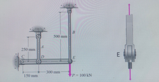
Bar B of the pin connected system is made of aluminum alloy (E=105 GPa, A=1200 mm^2) and bar A is made of a hardened carbon steel (E=210 GPa, A=1200 mm^2). Bar CDE is rigid. When the system is unloaded, Bars A and B are unstressed.
Determine:
a) The Normal Stress in bars A and B. (5pts)
b) The Shearing Stress in the 20-mm diameter pin E which is in double shear. (5pts)
c) If the yield stress of the material of the pin at E is 300 MPa, what is the factor of safety of the pin given the applied stresses? (3pts)
d) The vertical component of displacement of Pin E. (2 pts)
Homework Answers


Add Answer to:
Bar B of the pin connected system is made of aluminum alloy
(E=105 GPa, A=1200 mm^2)...
The pin-connected structure shown in Fig. 5 consists of a rigid bar ABCD and two 1,500-mm-long...
 The pin-connected structure shown in Fig. 5 consists of a rigid bar ABCD and two 1,500-mm-long bars. Bar (1) is steel [E=200 GPa] with a cross-sectional area of A1 = 510 mm2. Bar (2) is an aluminium alloy [E-70 GPa] with a cross-sectional area of A2 1,300 mm2. All bars are unstressed before the load P is applied. If a concentrated load of P 200 kN acts on the structure at D determine: (a) the normal stresses in both bars...
The rod ABCD is made of an aluminum alloy with a modulus of elasticity E = 70 GPa
 The rod ABCD is made of an aluminum alloy with a modulus of elasticity E = 70 GPa. For the loading shown, and neglecting the weight of the rod, determine the stress in sections AB, BC, and CD and the deflection of point D. For stress, answer to nearest whole number. Use 3 decimal places for displacement. Drawing is not to scale. Assume compressive stresses are positive, and that displacement to the right is positive. Stress in AB = _______ MPa Stress...
In the system, each element is made of aluminum. and E = 70 GPa. Cross sections...
 In the system, each element is made of aluminum.
and E = 70 GPa. Cross sections of vertical connections 10x40
Mm. For the upload shown
a) FC by taking pin diameters 10 mm only for this option
the greatest stress in the element.
b) Safety shear stress at point F for 75 MPa
the diameter of the pin,
c) Displacement of the G point,
You calculate.
250 mm 400 mm А B 250 mm 40 mm с E 300 mm...
In the system, each element is made of aluminum.
and E = 70 GPa. Cross sections of vertical connections 10x40
Mm. For the upload shown
a) FC by taking pin diameters 10 mm only for this option
the greatest stress in the element.
b) Safety shear stress at point F for 75 MPa
the diameter of the pin,
c) Displacement of the G point,
You calculate.
250 mm 400 mm А B 250 mm 40 mm с E 300 mm...
Chapter 5, Problem 35P Bookmark Show all steps ON Problem The pin-connected structure shown in Figure...
 Chapter 5, Problem 35P Bookmark Show all steps ON Problem The pin-connected structure shown in Figure P5.35/36 consists of a rigid beam ABCD and two supporting bars. Bar (1) is a bronze alloy [E105 GPa] with a cross-sectional area of A1 290 mm2. Bar (2) is an aluminum alloy [E70 GPa] with a cross-sectional area of A2 650 mm2. If a load of P 30 kN is applied at B, determine (a) the normal stresses in both bars (1) and...
The AB tube made of a magnesium alloy AM1004-T61 is covered with a rigid plate E. The spacing between E and the C-end of the CD solid circular bar, made of a 6061-T6 aluminum alloy, is 0.2mm when It...
 The AB tube made of a magnesium alloy AM1004-T61 is covered
with a rigid plate E. The spacing between E and the C-end of the CD
solid circular bar, made of a 6061-T6 aluminum alloy, is 0.2mm when
It has a temperature of 30 Centigrade. Deteremina:
a) Are the forces to which the AM1004-T61-76 tube is subjected
if the temperature of the magnesium tube rises to 130 C?
b) What is the deformation of each bar?
c) Do any of...
The AB tube made of a magnesium alloy AM1004-T61 is covered
with a rigid plate E. The spacing between E and the C-end of the CD
solid circular bar, made of a 6061-T6 aluminum alloy, is 0.2mm when
It has a temperature of 30 Centigrade. Deteremina:
a) Are the forces to which the AM1004-T61-76 tube is subjected
if the temperature of the magnesium tube rises to 130 C?
b) What is the deformation of each bar?
c) Do any of...
The cylindrical pressure vessel shown in the figure has an inside diameter of 980 mm and a wall thickness of 12 mm. The cylinder is made of an aluminum alloy that has an elastic modulus of E = 72 GPa...
 The cylindrical pressure vessel shown in the figure has an
inside diameter of 980 mm and a wall thickness of 12 mm. The
cylinder is made of an aluminum alloy that has an elastic modulus
of E = 72 GPa and a shear modulus of G = 27.5
GPa. Two strain gages are mounted on the exterior surface of the
cylinder at right angles to each other. The angle θ is 21°. If the
pressure in the vessel is 1.86...
The cylindrical pressure vessel shown in the figure has an
inside diameter of 980 mm and a wall thickness of 12 mm. The
cylinder is made of an aluminum alloy that has an elastic modulus
of E = 72 GPa and a shear modulus of G = 27.5
GPa. Two strain gages are mounted on the exterior surface of the
cylinder at right angles to each other. The angle θ is 21°. If the
pressure in the vessel is 1.86...
2) The rigid bar CDE is attached to a pin support at E and rests on...
 2) The rigid bar CDE is attached to a pin support at E and rests on the 30-mm diameter brass cylinder BD. A 22-mm-diameter steel rod AC passes through a hole in the bar and is secured by a nut which is snugly fitted when the temperature of the entire assembly is 20°C. The temperature of the brass cylinder is then raised to 50°C while the steel rod remains at 20°C. Assuming that no stresses were present before the temperature...
The rigid beam in (Figure 1) is supported by the three suspender bars. Bars AB and EF are made of aluminum and bar CD is made of steel.
 The rigid beam in (Figure 1) is supported by the three suspender bars. Bars AB and EF are made of aluminum and bar CD is made of steel. Part A If each bar has a cross-sectional area of \(480 \mathrm{~mm}^{2}\), determine the maximum value of \(P\) if the allowable stress is \(\left(\sigma_{\text {allow }}\right)_{\text {st }}-190 \mathrm{MPa}\) far the steel and \(\left(\sigma_{\text {allow }}\right)_{\text {al }}-150 \mathrm{MPa}\) for the aluminum. \(E_{\text {st }}-200 \mathrm{GPa}, E_{\text {al }}-70 \mathrm{GPa}\).
2) The rigid bar CDE is attached to a pin support at E and rests on...
 2) The rigid bar CDE is attached to a pin support at E and rests on the 30-mm diameter brass cylinder BD. A 22-mm-diameter steel rod AC passes through a hole in the bar and is secured by a nut which is snugly fitted when the temperature of the entire assembly is 20°C. The temperature of the brass cylinder is then raised to 50°C while the steel rod remains at 20°C. Assuming that no stresses were present before the temperature...
 The pin-connected structure shown in Fig. 5 consists of a rigid bar ABCD and two 1,500-mm-long bars. Bar (1) is steel [E=200 GPa] with a cross-sectional area of A1 = 510 mm2. Bar (2) is an aluminium alloy [E-70 GPa] with a cross-sectional area of A2 1,300 mm2. All bars are unstressed before the load P is applied. If a concentrated load of P 200 kN acts on the structure at D determine: (a) the normal stresses in both bars...
 In the system, each element is made of aluminum.
and E = 70 GPa. Cross sections of vertical connections 10x40
Mm. For the upload shown
a) FC by taking pin diameters 10 mm only for this option
the greatest stress in the element.
b) Safety shear stress at point F for 75 MPa
the diameter of the pin,
c) Displacement of the G point,
You calculate.
250 mm 400 mm А B 250 mm 40 mm с E 300 mm...
In the system, each element is made of aluminum.
and E = 70 GPa. Cross sections of vertical connections 10x40
Mm. For the upload shown
a) FC by taking pin diameters 10 mm only for this option
the greatest stress in the element.
b) Safety shear stress at point F for 75 MPa
the diameter of the pin,
c) Displacement of the G point,
You calculate.
250 mm 400 mm А B 250 mm 40 mm с E 300 mm...
 Chapter 5, Problem 35P Bookmark Show all steps ON Problem The pin-connected structure shown in Figure P5.35/36 consists of a rigid beam ABCD and two supporting bars. Bar (1) is a bronze alloy [E105 GPa] with a cross-sectional area of A1 290 mm2. Bar (2) is an aluminum alloy [E70 GPa] with a cross-sectional area of A2 650 mm2. If a load of P 30 kN is applied at B, determine (a) the normal stresses in both bars (1) and...
 The AB tube made of a magnesium alloy AM1004-T61 is covered
with a rigid plate E. The spacing between E and the C-end of the CD
solid circular bar, made of a 6061-T6 aluminum alloy, is 0.2mm when
It has a temperature of 30 Centigrade. Deteremina:
a) Are the forces to which the AM1004-T61-76 tube is subjected
if the temperature of the magnesium tube rises to 130 C?
b) What is the deformation of each bar?
c) Do any of...
The AB tube made of a magnesium alloy AM1004-T61 is covered
with a rigid plate E. The spacing between E and the C-end of the CD
solid circular bar, made of a 6061-T6 aluminum alloy, is 0.2mm when
It has a temperature of 30 Centigrade. Deteremina:
a) Are the forces to which the AM1004-T61-76 tube is subjected
if the temperature of the magnesium tube rises to 130 C?
b) What is the deformation of each bar?
c) Do any of...
 The cylindrical pressure vessel shown in the figure has an
inside diameter of 980 mm and a wall thickness of 12 mm. The
cylinder is made of an aluminum alloy that has an elastic modulus
of E = 72 GPa and a shear modulus of G = 27.5
GPa. Two strain gages are mounted on the exterior surface of the
cylinder at right angles to each other. The angle θ is 21°. If the
pressure in the vessel is 1.86...
The cylindrical pressure vessel shown in the figure has an
inside diameter of 980 mm and a wall thickness of 12 mm. The
cylinder is made of an aluminum alloy that has an elastic modulus
of E = 72 GPa and a shear modulus of G = 27.5
GPa. Two strain gages are mounted on the exterior surface of the
cylinder at right angles to each other. The angle θ is 21°. If the
pressure in the vessel is 1.86...
 2) The rigid bar CDE is attached to a pin support at E and rests on the 30-mm diameter brass cylinder BD. A 22-mm-diameter steel rod AC passes through a hole in the bar and is secured by a nut which is snugly fitted when the temperature of the entire assembly is 20°C. The temperature of the brass cylinder is then raised to 50°C while the steel rod remains at 20°C. Assuming that no stresses were present before the temperature...
 2) The rigid bar CDE is attached to a pin support at E and rests on the 30-mm diameter brass cylinder BD. A 22-mm-diameter steel rod AC passes through a hole in the bar and is secured by a nut which is snugly fitted when the temperature of the entire assembly is 20°C. The temperature of the brass cylinder is then raised to 50°C while the steel rod remains at 20°C. Assuming that no stresses were present before the temperature...
Most questions answered within 3 hours.
-
Using MARS simulator, write MIPS programs according to
the following scenarios: Receive a positive integer number...
asked 42 minutes ago -
An object in front of a concave mirror has a real image that is
11.5 cm...
asked 56 minutes ago -
Consider the reaction, C3 H8 + O2 --> CO2 + H2O. How many
moles of O2...
asked 2 hours ago -
You and your opponent both roll a fair die. If you both roll the
same number,...
asked 2 hours ago -
In a study of the accuracy of fast food drive-through orders,
Restaurant A had 257 accurate...
asked 2 hours ago -
Identify and describe in detail the four categories of
institutions that could be included in a...
asked 3 hours ago -
In python
class Customer:
def __init__(self, customer_id, last_name, first_name, phone_number, address):
self._customer_id = int(customer_id)
self._last_name =...
asked 3 hours ago -
What is an example of a limitation in implementing a new
ERP system and how it...
asked 3 hours ago -
In a section of 9.7cm of an artery with a radius of 2.6mm there
is a...
asked 3 hours ago -
the two carboxylic acid groups of aspartic acid have different
acidities with pKa values of 2.1...
asked 3 hours ago -
Would CuCO3 aqueous salt combined with calcium chloride
form a solid precipitate? If so, what would...
asked 3 hours ago -
How do ECM Solutions assist in embedding a culture of continuous
improvement in an organization? (Project...
asked 3 hours ago