![C5 Quiz, Water flows steadily down the inclined pipe as indicated in Figure below. Determine the following (a) [5] the difference in pressure prp (b) [5] the loss in [ft] between section (1) and (2) 1 psi- 144 Ilb/f 5 It Section (1) 30° Section 12) Mercury](http://img.homeworklib.com/questions/af17e2f0-2a22-11eb-ad79-0535a6b5fe39.png?x-oss-process=image/resize,w_560)
Homework Answers

Add Answer to:
Fluid Mechanics
C5 Quiz, Water flows steadily down the inclined pipe as indicated in Figure below....
Example #6: Water flows steadily down the inclined pipe as indicated in Fig P5.131. Determine the...
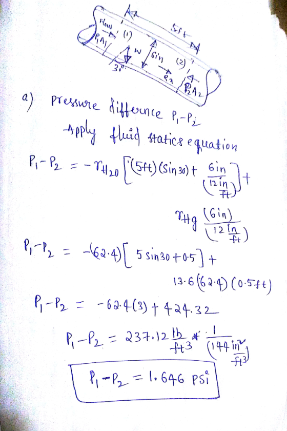
 Example #6: Water flows steadily down the inclined pipe as indicated in Fig P5.131. Determine the following: (a) the difference in pressure P.-P2. (b) the loss between sections (1) and (2), (c) the net axial force exerted by the pipe wall on the flowing water between sections (1) and (2). Flow Section (1) 5 t 6 in. 30 Section (2) 6 in. Mercury By Asest
Attached figure shows part of a network in which water flows steadily up an inclined pipe. Determine: a) The difference...
 Attached figure shows part of a network in which water flows steadily up an inclined pipe. Determine: a) The difference in pressure (P- P2) if L=10 ft, h=12 in, 0=45° and d-6 in b) The head loss between stations 1 and 2 c) The net axial force exerted by the pipe wall on the flowing water between stations 1 and 2 2.L T Water Water Hg
Attached figure shows part of a network in which water flows steadily up an...
Attached figure shows part of a network in which water flows steadily up an inclined pipe. Determine: a) The difference in pressure (P- P2) if L=10 ft, h=12 in, 0=45° and d-6 in b) The head loss between stations 1 and 2 c) The net axial force exerted by the pipe wall on the flowing water between stations 1 and 2 2.L T Water Water Hg
Attached figure shows part of a network in which water flows steadily up an...
Water flows steadily downwards through a circular pipe of internal diameter 0.15 m inclined at 30°...
 Water flows steadily downwards through a circular pipe of internal diameter 0.15 m inclined at 30° to the horizontal. A U-tube manometer is used to determine the pressure difference between two points displaced axially along the pipe by a distance 1.25 m. The reading on the manometer is 0.25 m of mercury. 1.25 m 0.15 m 30 0.25 m mercury Figure 2: Manometer and pipe Neglecting the thickness of the wall, determine between points 1 and 2: a. The difference...
1. (20 points) Below, a fluid mechanics probiem with two major errors is shown. Water fiows...
 1. (20 points) Below, a fluid mechanics probiem with two major errors is shown. Water fiows steadily upward through a pipe consisting of two sections with a smooth reducing section. Using the given information below, find the height difference 'h' from the mercury manometer. Friction is negligible in this flow. The density of mercury and water are given as pe 847 Ibm/f3 and pu 62.4 lbm/ft respectiveiy A1 0.08 ft2 42 0.05 ft V1 8 ft/s V2 15 ft/s P,...
Engineering Fluid Mechanics PO 17: Water flows through a section of a pipe of length L...
 Engineering Fluid Mechanics
PO 17: Water flows through a section of a pipe of length L and diameter D as indicated in the figure. The pipe has a roughness of k, = 0.3mm. The discharge is Q = 1m/s. The kinematic viscosity of water is V = 10 m/s. (a) What is the friction factor ? (Moody diagram on next page). (b) What is the head loss over the pipe section of length L? (c) What horizontal force is required...
Engineering Fluid Mechanics
PO 17: Water flows through a section of a pipe of length L and diameter D as indicated in the figure. The pipe has a roughness of k, = 0.3mm. The discharge is Q = 1m/s. The kinematic viscosity of water is V = 10 m/s. (a) What is the friction factor ? (Moody diagram on next page). (b) What is the head loss over the pipe section of length L? (c) What horizontal force is required...
Part 1 s the loss between sections (1) and (21. and Water flows steadily down the...
 Part 1 s the loss between sections (1) and (21. and Water flows steadily down the inclined pipe as indicated in the figure below. Determine the following a the difference in pressure i e) the net axial force orted by the pipe wall on the flowing water between sections (1) and 121 Assume 5 in 8 = 32" Concept Pressure changes for a flow in a p re dependent on the flow velocities elevat on the transfer of mechanical work...
Carefully understand the concept and ansewr. FLuid Mechanics Consider a pipe system as shown in Figure...
 Carefully understand the concept and ansewr. FLuid Mechanics
Consider a pipe system as shown in Figure 1. The pipe is connected to a mercury manometer at point 1 and point 2. Prove that the pipe wall between these points is exerting less than 600 N of fluid force. The frictional losses along the pipe is not negligible Water 1.5 m 1 0.15 m 2. 30° 0.15 m Mercury,SG 13.5
Carefully understand the concept and ansewr. FLuid Mechanics
Consider a pipe system as shown in Figure 1. The pipe is connected to a mercury manometer at point 1 and point 2. Prove that the pipe wall between these points is exerting less than 600 N of fluid force. The frictional losses along the pipe is not negligible Water 1.5 m 1 0.15 m 2. 30° 0.15 m Mercury,SG 13.5
Optional- Quiz 12 Instructor Trung Bao Le, PhD, Dept. CEE, NDSU CE309-Fluid Mechanics-Fall 2018 November 17,...
 Optional- Quiz 12 Instructor Trung Bao Le, PhD, Dept. CEE, NDSU CE309-Fluid Mechanics-Fall 2018 November 17, 2018 Due date: 9:00 AM Wednesday, November 21, 2018 Question Water flows from the basement to the second floor through the 0.75-in- diameter copper pipe (e 0.000005 ft) at a flow rate 12.0gal/min- 0.0267ft% and exits through a faucet of diameter 0.5 in as shown in Figure 1. The minor loss coefficients of the components are: K 1.5 for each elbow K10 for the...
thermaldynamics and fluid mechanics Question 4 An orifice plate flow meter, as shown in figure Q4,...
 thermaldynamics and fluid mechanics
Question 4 An orifice plate flow meter, as shown in figure Q4, is situated in a horizontal pipe of 95 cm diameter (d) in which water flows. The pressure difference between the vena contracta and flow upstream at point 1 is measured using a differential manometer. The diameter of the sharp-edged orifice (d.) is 35 cm. The coefficient of discharge for the flow meter is 0.7, and the coefficient of contraction is 0.62. Assume the density...
thermaldynamics and fluid mechanics
Question 4 An orifice plate flow meter, as shown in figure Q4, is situated in a horizontal pipe of 95 cm diameter (d) in which water flows. The pressure difference between the vena contracta and flow upstream at point 1 is measured using a differential manometer. The diameter of the sharp-edged orifice (d.) is 35 cm. The coefficient of discharge for the flow meter is 0.7, and the coefficient of contraction is 0.62. Assume the density...
 Example #6: Water flows steadily down the inclined pipe as indicated in Fig P5.131. Determine the following: (a) the difference in pressure P.-P2. (b) the loss between sections (1) and (2), (c) the net axial force exerted by the pipe wall on the flowing water between sections (1) and (2). Flow Section (1) 5 t 6 in. 30 Section (2) 6 in. Mercury By Asest
 Attached figure shows part of a network in which water flows steadily up an inclined pipe. Determine: a) The difference in pressure (P- P2) if L=10 ft, h=12 in, 0=45° and d-6 in b) The head loss between stations 1 and 2 c) The net axial force exerted by the pipe wall on the flowing water between stations 1 and 2 2.L T Water Water Hg
Attached figure shows part of a network in which water flows steadily up an...
Attached figure shows part of a network in which water flows steadily up an inclined pipe. Determine: a) The difference in pressure (P- P2) if L=10 ft, h=12 in, 0=45° and d-6 in b) The head loss between stations 1 and 2 c) The net axial force exerted by the pipe wall on the flowing water between stations 1 and 2 2.L T Water Water Hg
Attached figure shows part of a network in which water flows steadily up an...
 Water flows steadily downwards through a circular pipe of internal diameter 0.15 m inclined at 30° to the horizontal. A U-tube manometer is used to determine the pressure difference between two points displaced axially along the pipe by a distance 1.25 m. The reading on the manometer is 0.25 m of mercury. 1.25 m 0.15 m 30 0.25 m mercury Figure 2: Manometer and pipe Neglecting the thickness of the wall, determine between points 1 and 2: a. The difference...
 1. (20 points) Below, a fluid mechanics probiem with two major errors is shown. Water fiows steadily upward through a pipe consisting of two sections with a smooth reducing section. Using the given information below, find the height difference 'h' from the mercury manometer. Friction is negligible in this flow. The density of mercury and water are given as pe 847 Ibm/f3 and pu 62.4 lbm/ft respectiveiy A1 0.08 ft2 42 0.05 ft V1 8 ft/s V2 15 ft/s P,...
 Engineering Fluid Mechanics
PO 17: Water flows through a section of a pipe of length L and diameter D as indicated in the figure. The pipe has a roughness of k, = 0.3mm. The discharge is Q = 1m/s. The kinematic viscosity of water is V = 10 m/s. (a) What is the friction factor ? (Moody diagram on next page). (b) What is the head loss over the pipe section of length L? (c) What horizontal force is required...
Engineering Fluid Mechanics
PO 17: Water flows through a section of a pipe of length L and diameter D as indicated in the figure. The pipe has a roughness of k, = 0.3mm. The discharge is Q = 1m/s. The kinematic viscosity of water is V = 10 m/s. (a) What is the friction factor ? (Moody diagram on next page). (b) What is the head loss over the pipe section of length L? (c) What horizontal force is required...
 Part 1 s the loss between sections (1) and (21. and Water flows steadily down the inclined pipe as indicated in the figure below. Determine the following a the difference in pressure i e) the net axial force orted by the pipe wall on the flowing water between sections (1) and 121 Assume 5 in 8 = 32" Concept Pressure changes for a flow in a p re dependent on the flow velocities elevat on the transfer of mechanical work...
 Carefully understand the concept and ansewr. FLuid Mechanics
Consider a pipe system as shown in Figure 1. The pipe is connected to a mercury manometer at point 1 and point 2. Prove that the pipe wall between these points is exerting less than 600 N of fluid force. The frictional losses along the pipe is not negligible Water 1.5 m 1 0.15 m 2. 30° 0.15 m Mercury,SG 13.5
Carefully understand the concept and ansewr. FLuid Mechanics
Consider a pipe system as shown in Figure 1. The pipe is connected to a mercury manometer at point 1 and point 2. Prove that the pipe wall between these points is exerting less than 600 N of fluid force. The frictional losses along the pipe is not negligible Water 1.5 m 1 0.15 m 2. 30° 0.15 m Mercury,SG 13.5
 Optional- Quiz 12 Instructor Trung Bao Le, PhD, Dept. CEE, NDSU CE309-Fluid Mechanics-Fall 2018 November 17, 2018 Due date: 9:00 AM Wednesday, November 21, 2018 Question Water flows from the basement to the second floor through the 0.75-in- diameter copper pipe (e 0.000005 ft) at a flow rate 12.0gal/min- 0.0267ft% and exits through a faucet of diameter 0.5 in as shown in Figure 1. The minor loss coefficients of the components are: K 1.5 for each elbow K10 for the...
 thermaldynamics and fluid mechanics
Question 4 An orifice plate flow meter, as shown in figure Q4, is situated in a horizontal pipe of 95 cm diameter (d) in which water flows. The pressure difference between the vena contracta and flow upstream at point 1 is measured using a differential manometer. The diameter of the sharp-edged orifice (d.) is 35 cm. The coefficient of discharge for the flow meter is 0.7, and the coefficient of contraction is 0.62. Assume the density...
thermaldynamics and fluid mechanics
Question 4 An orifice plate flow meter, as shown in figure Q4, is situated in a horizontal pipe of 95 cm diameter (d) in which water flows. The pressure difference between the vena contracta and flow upstream at point 1 is measured using a differential manometer. The diameter of the sharp-edged orifice (d.) is 35 cm. The coefficient of discharge for the flow meter is 0.7, and the coefficient of contraction is 0.62. Assume the density...
Most questions answered within 3 hours.
-
Refer to the following lease amortization schedule. The 10
payments are made annually starting with the...
asked 10 minutes ago -
Explain how God fits into Aquinas' theory of happiness.
asked 17 minutes ago -
1.1 With aid of diagrams and suitable examples discuss
the economic effects of price controls.
1.2...
asked 22 minutes ago -
When the nuclide polonium-214 undergoes alpha
decay:
The name of the product nuclide is .
The...
asked 36 minutes ago -
Q. The market demand function is D(Pd) = 160 - 2Pd and the
market supply function...
asked 41 minutes ago -
An unknown alcohol is analyzed by freezing point depression. The
unknown is either methanol (CH3OH), ethanol...
asked 42 minutes ago -
As a person inhales, air moves down the windpipe (bronchus),
through a constriction where the air...
asked 44 minutes ago -
Youngchang Keyboard sells a $1400 keyboard on a monthly payment
plan over 2 years.
a) If...
asked 51 minutes ago -
For a one step reaction, the activation energy for the
forward reaction is 40.0 kJ mol-1,...
asked 54 minutes ago -
1. A good thesis statement _____ .
is limited but not too narrow
is very broad...
asked 49 minutes ago -
What is the main use of a transistor and what is an Integrated
Circuit?
asked 57 minutes ago -
Intro to Java Programming
Write a method named isDivisible that takes two integers, n
and m,...
asked 55 minutes ago