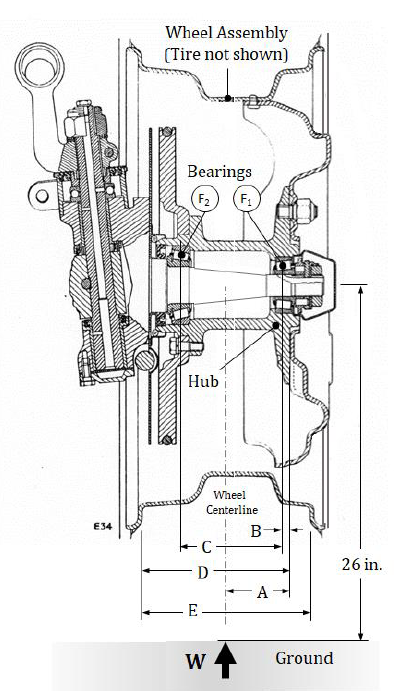
Reaction Forces on Bearings
Assuming a factor of safety of 1.75 (i.e. multiply the given load W by 1.75), determine the bearing reaction forces (F1 and F2). Bearing F1 has an inner diameter of 1-3/4 in. while bearing F2 has an inner diameter of 2-1/4 in.
Homework Answers
Request Answer!
We need at least 10 more requests to produce the answer.
0 / 10 have requested this problem solution
The more requests, the faster the answer.
augue application? 6-10 A rotating shaft of 25-mm diameter is simply supported by bearing reaction forces R and R2. The...
 augue application? 6-10 A rotating shaft of 25-mm diameter is simply supported by bearing reaction forces R and R2. The shaft is loaded with a transverse load of 13 kN as shown in the figure. The shaft is made from AISI 1045 hot-rolled steel. The surface has been machined. Determine (a) the minimum static factor of safety based on yielding. (b) the endurance limit, adjusted as necessary with Marin factors. (c) the minimum fatigue factor of safety based on achieving...
A rotating shaft of 25-mm diameter is simply supported by bearing reaction forces R and R. The shaft is loaded with a transverse load of 13 kN as shown in the figure.
 A rotating shaft of 25-mm diameter is simply supported by bearing reaction forces R and R. The shaft is loaded with a transverse load of 13 kN as shown in the figure. The shaft is made from AISI 1045 hot-rolled steel. The surface has been machined. Determine (a) the minimum static factor of safety based on yielding. (b) the endurance limit, adjusted as necessary with Marin factors. (c) the minimum fatigue factor of safety based on achieving infinite life. (d) If the fatigue factor...
System Description The system is made of a shaft with two bearings and two pulleys as...
 System Description The system is made of a shaft with two bearings and two pulleys as shown in figure 1 D1 = D2 6 inches 4 inches 3 inches 120 lbf 35 lbf Axial Force N 1.5" motor shaft D1 02 Bearing I Bearing lI Pulley 2 Pulley 1 Pulley 2 Figure 1 Questions Given the following THE SHAFT IS NOT ROTATING FOR QUESTIONS 1 -5 THE AXIAL FORCE N 550 lbf THERE ARE NO FORCES ON PULLEY 1 Op=...
Pulley Diameter = 800 mm Base Plate Diameter = 1200 mm Shaft Mounted Wheel Axial force...
 Pulley Diameter = 800 mm Base Plate Diameter = 1200 mm Shaft Mounted Wheel Axial force F2 along the shaft axis Belt connected to motor with tension force F Figure 1. Side View Belt Bearing A. Bearing B FR = 2 kN --- - - - - - - - - - - > ---- 500 mm 500 mm 500 mm F1 = 500 N 'Fw = 1 kN Figure 2. The design of a fatigue test machine for car...
2. Preliminary force analysis of the shaft in Problem 1 suggests that the reaction forces on the ...
 please solve #2
shaft from #1 above
2. Preliminary force analysis of the shaft in Problem 1 suggests that the reaction forces on the right side bearing are as follows: F-24 kN-5 = 3.35 kN, and = 1.5 kN. Size an angular contact bearing for the right side of the shaft for 10 kh of operation at 1400 RPM. Assume 92% reliability, ka-1. Is the large diameter of the shaft shoulder (52 mm) appropriately sized for the bearing you selected?...
please solve #2
shaft from #1 above
2. Preliminary force analysis of the shaft in Problem 1 suggests that the reaction forces on the right side bearing are as follows: F-24 kN-5 = 3.35 kN, and = 1.5 kN. Size an angular contact bearing for the right side of the shaft for 10 kh of operation at 1400 RPM. Assume 92% reliability, ka-1. Is the large diameter of the shaft shoulder (52 mm) appropriately sized for the bearing you selected?...
6. For the bearing with the largest radial load and without knowing the shaft diameter, what...
 6. For the bearing with the largest radial load and without
knowing the shaft diameter, what would be the catalog rating for a
radially loaded ball bearing to withstand 1000 x 10e6 cycles with
90% reliability. The bearing manufacturer rates its bearing for a
million cycles.
7. A 10 mm diameter steel shaft is subject to bending stresses
only. The material has Sut = 1100 MPa and Sy = 950 MPa and a
fine-ground surface finish.
1. Determine the factor...
6. For the bearing with the largest radial load and without
knowing the shaft diameter, what would be the catalog rating for a
radially loaded ball bearing to withstand 1000 x 10e6 cycles with
90% reliability. The bearing manufacturer rates its bearing for a
million cycles.
7. A 10 mm diameter steel shaft is subject to bending stresses
only. The material has Sut = 1100 MPa and Sy = 950 MPa and a
fine-ground surface finish.
1. Determine the factor...
The shaft in the figure below is supported on journal bearings that do not offer any resistance t...
 The shaft in the figure below is supported on journal bearings that do not offer any resistance to axial load. The yield strength of the material is Ơ,-300 MPa and the safety factor is FS-2.5 1) 2) 3) 4) Determine the reaction at the supports. Draw the shear force, bending and torsion moment diagrams Derive an expression for the components of the stress tensor at a cross section of the shaft Neglect the shear stress due to the transverse shear...
The shaft shown in Figure is supported by bearings cach end, which have bores of 20.0...
 The shaft shown in Figure is supported by bearings cach end, which have bores of 20.0 mm. Design the shaft to carry the given load if it is steady and the shaft is stationary. Make the dimension a as large as possible while keeping the stress safe. Determine the required diameter in the middle portion. The maximum fillet permissible is 2.0 mm. Use SAE 1137 cold-drawn steel. Use a design factor of 3 The material properties are as follows:- Q-1...
The shaft shown in the figure is machined from AISI 1040 CD steel and is supported in rolling bearings at A and B.
 The shaft shown in the figure is machined from AISI 1040 CD steel and is supported in rolling bearings at A and B. The applied forces F1 = 1500 lbf and F2 = 3000 lbf are coming off of gears located at respective positions. The shaft rotates at 2000 rpm while transmitting 50hp between the gears. Determine the minimum fatigue factor of safety based on achieving infinite life using Modified- Goodman theory. If infinite life is not predicted, estimate the...
3. A beam with a hollow circular cross section of outer diameter D and inner diameter...
 3. A beam with a hollow circular cross section of outer diameter D and inner diameter d. The length Lis fixed at a wall. Consider the following loading conditions, all applied to the beam at the midpoint of length L. For each loading scheme state determine the magnitude of that stress in terms of the variables given in the problem). (5 points) i. ii. iii. iv. V. Normal stress due to axial load F Shear stress due to torque T...
 augue application? 6-10 A rotating shaft of 25-mm diameter is simply supported by bearing reaction forces R and R2. The shaft is loaded with a transverse load of 13 kN as shown in the figure. The shaft is made from AISI 1045 hot-rolled steel. The surface has been machined. Determine (a) the minimum static factor of safety based on yielding. (b) the endurance limit, adjusted as necessary with Marin factors. (c) the minimum fatigue factor of safety based on achieving...
 System Description The system is made of a shaft with two bearings and two pulleys as shown in figure 1 D1 = D2 6 inches 4 inches 3 inches 120 lbf 35 lbf Axial Force N 1.5" motor shaft D1 02 Bearing I Bearing lI Pulley 2 Pulley 1 Pulley 2 Figure 1 Questions Given the following THE SHAFT IS NOT ROTATING FOR QUESTIONS 1 -5 THE AXIAL FORCE N 550 lbf THERE ARE NO FORCES ON PULLEY 1 Op=...
 Pulley Diameter = 800 mm Base Plate Diameter = 1200 mm Shaft Mounted Wheel Axial force F2 along the shaft axis Belt connected to motor with tension force F Figure 1. Side View Belt Bearing A. Bearing B FR = 2 kN --- - - - - - - - - - - > ---- 500 mm 500 mm 500 mm F1 = 500 N 'Fw = 1 kN Figure 2. The design of a fatigue test machine for car...
 please solve #2
shaft from #1 above
2. Preliminary force analysis of the shaft in Problem 1 suggests that the reaction forces on the right side bearing are as follows: F-24 kN-5 = 3.35 kN, and = 1.5 kN. Size an angular contact bearing for the right side of the shaft for 10 kh of operation at 1400 RPM. Assume 92% reliability, ka-1. Is the large diameter of the shaft shoulder (52 mm) appropriately sized for the bearing you selected?...
please solve #2
shaft from #1 above
2. Preliminary force analysis of the shaft in Problem 1 suggests that the reaction forces on the right side bearing are as follows: F-24 kN-5 = 3.35 kN, and = 1.5 kN. Size an angular contact bearing for the right side of the shaft for 10 kh of operation at 1400 RPM. Assume 92% reliability, ka-1. Is the large diameter of the shaft shoulder (52 mm) appropriately sized for the bearing you selected?...
 6. For the bearing with the largest radial load and without
knowing the shaft diameter, what would be the catalog rating for a
radially loaded ball bearing to withstand 1000 x 10e6 cycles with
90% reliability. The bearing manufacturer rates its bearing for a
million cycles.
7. A 10 mm diameter steel shaft is subject to bending stresses
only. The material has Sut = 1100 MPa and Sy = 950 MPa and a
fine-ground surface finish.
1. Determine the factor...
6. For the bearing with the largest radial load and without
knowing the shaft diameter, what would be the catalog rating for a
radially loaded ball bearing to withstand 1000 x 10e6 cycles with
90% reliability. The bearing manufacturer rates its bearing for a
million cycles.
7. A 10 mm diameter steel shaft is subject to bending stresses
only. The material has Sut = 1100 MPa and Sy = 950 MPa and a
fine-ground surface finish.
1. Determine the factor...
 The shaft in the figure below is supported on journal bearings that do not offer any resistance to axial load. The yield strength of the material is Ơ,-300 MPa and the safety factor is FS-2.5 1) 2) 3) 4) Determine the reaction at the supports. Draw the shear force, bending and torsion moment diagrams Derive an expression for the components of the stress tensor at a cross section of the shaft Neglect the shear stress due to the transverse shear...
 The shaft shown in Figure is supported by bearings cach end, which have bores of 20.0 mm. Design the shaft to carry the given load if it is steady and the shaft is stationary. Make the dimension a as large as possible while keeping the stress safe. Determine the required diameter in the middle portion. The maximum fillet permissible is 2.0 mm. Use SAE 1137 cold-drawn steel. Use a design factor of 3 The material properties are as follows:- Q-1...
 3. A beam with a hollow circular cross section of outer diameter D and inner diameter d. The length Lis fixed at a wall. Consider the following loading conditions, all applied to the beam at the midpoint of length L. For each loading scheme state determine the magnitude of that stress in terms of the variables given in the problem). (5 points) i. ii. iii. iv. V. Normal stress due to axial load F Shear stress due to torque T...
Most questions answered within 3 hours.
-
A box of mass m = 2.00 kg is positioned on a ramp at an angle...
asked 40 seconds ago -
Wheel A has three times the moment of inertia about its axis of
rotation as wheel...
asked 5 minutes ago -
A boy pulls a 20.0-kg box with a 160-N force at 39° above a
horizontal surface....
asked 5 minutes ago -
Determine if a 10-ft. long 6 x14 beam is adequate to support a
dead load wD=...
asked 7 minutes ago -
A distribution of values is normal with a mean of 157.8 and a
standard deviation of...
asked 36 minutes ago -
Suppose the demand for crossing the Brooklyn Bridge is given by
Q = 10,000 - 1000P....
asked 40 minutes ago -
Assume that we are in a Heckscher Ohlin world: 2 Two countries:
Home (H) and Foreign...
asked 41 minutes ago -
A nationally known supermarket decided to promote its own brand
of soft drinks on TV for...
asked 59 minutes ago -
A bond issued by IBM on December 1, 1996, is scheduled to mature
on December 1,...
asked 1 hour ago -
Answer questions 17-19 below using the following information: A
firm is producing in the short-run (with...
asked 1 hour ago -
an overhead electric power line carries a maximum current of 250
A. what is the magnitude...
asked 1 hour ago -
Paul Gray mentioned he was concerned about the security of his
clients and their own management...
asked 3 hours ago