
Homework Answers
Add Answer to:
4. An Am1004-T61 magnesium tube is bonded to a central A36 steel rod. Sketch and label...
4. An Am1004-T61 magnesium tube is bonded to a central A36 steel rod. Sketch and label...
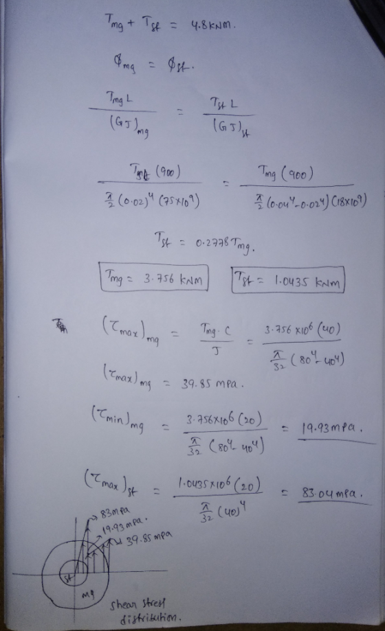
 4. An Am1004-T61 magnesium tube is bonded to a central A36 steel rod. Sketch and label the shear stress distribution across the entire radius of the composite member when a torque of 4.8 kN-m is applied. Sketch the corresponding shear strain distribution. 900 mm 80 mimA 40 mm 80 mm4 40 mm 5. For the composite member of Problem 4, assume that both materials are perfectly plastic once they yield. Furthermore, assume that the shear yield stress of the magnesium...
Problem 1: The Am1004-T61 magnesium tube is bonded to the A36 steel rod. If the allowable...
 Problem 1: The Am1004-T61 magnesium tube is bonded to the A36 steel rod. If the allowable shear stress for the magnesium and steel are 45 MPa and 75 MPa respectively, determine the maximum torque that can be applied at A. Also determine the corresponding angle of twist. G-75GPa, Gmg=18GPa. shor sless mages
How would you draw the corresponding FBD and torque diagram? A magnesium tube (G-18GPa) of outer...
 How would you draw the corresponding FBD and torque
diagram?
A magnesium tube (G-18GPa) of outer diameter 80mm and length 1m is completely bonded to a steel rod (G 75GPa) of diameter 40mm and length 1.5m as shown. Both are fixed to the wall at A. When the two external torques shown are applied to the composite shaft: (1) Draw the corresponding FBDs and torque diagram, (2) Determine the minimum and maximum shear stress 25 kN-m magnitudes in the magnesium...
How would you draw the corresponding FBD and torque
diagram?
A magnesium tube (G-18GPa) of outer diameter 80mm and length 1m is completely bonded to a steel rod (G 75GPa) of diameter 40mm and length 1.5m as shown. Both are fixed to the wall at A. When the two external torques shown are applied to the composite shaft: (1) Draw the corresponding FBDs and torque diagram, (2) Determine the minimum and maximum shear stress 25 kN-m magnitudes in the magnesium...
(3pts): The truss is constructed of A36 steel (E -2 a cross-sectional area of 250 mm2. Answer the following s 300 Clbe wna -250 MES, AI 00 G Pa and O, 250 MPa). All truss members have (a) Determi...
 (3pts): The truss is constructed of A36 steel (E -2 a cross-sectional area of 250 mm2. Answer the following s 300 Clbe wna -250 MES, AI 00 G Pa and O, 250 MPa). All truss members have (a) Determine the normal stress and strain in member CD. (b) The support at joint D uses a pin placed in double shear. The pin diameter is 20 mm Determine the average shear stress acting in the pin. 50 kN 50 kN 25...
1. A solid steel bar of diameter d; = 25.0 mm is enclosed by a steel...
 1. A solid steel bar of diameter d; = 25.0 mm is enclosed by a steel tube of outer diameter d3 = 37.5 mm and inner diameter d2 = 30.0 mm (see figure). Both bar and tube are held rigidly by a support at end A and joined securely to a rigid plate at end B. The composite bar has a length L = 600 mm and is twisted Tube by a torque T = 400 N-m acting on the...
The 2014-T6 aluminum rod AC is reinforced with the firmly bonded A992 steel tube BC
 The 2014-T6 aluminum rod AC is reinforced with the firmly bonded A992 steel tube BC. (Figure 1) When no load is applied to the assembly, the gap between end C and the rigid support is 0.5 mm. Part A Determine the support reaction at C when an axial force of P= 340 kN is applied. Part B Determine the support reaction at D when an axial force of P = 340 kN is applied.
The 2014-T6 aluminum rod AC is reinforced with the firmly bonded A992 steel tube BC. (Figure...
 The 2014-T6 aluminum rod AC is reinforced with the firmly bonded A992 steel tube BC. (Figure 1) When no load is applied to the assembly, the gap between end and the rigid support is 0.5 mm. Part A Determine the support reaction at C when an axial force of P = 515 kN is applied. Express your answer to three significant figures and include appropriate units. UA C ? Value Units Submit Request Answer Part B Figure 1 1 of...
Question A-36 steel pipe with an outer diameter of 100 mm and an inner diameter of...
 Question A-36 steel pipe with an outer diameter of 100 mm and an inner diameter of 80 mm subjected to loadings shown in Figure 1. The pipe is rigidly fixed at B and P - 150 kN. Given the yield stress, Oy -250 MPa and factor of safety, F.S. - 1.5 is used against yielding on this entire pipe. (a) For the stress state at the surface, construct the Mohr circle and determine: (1) the total stresses at surface of...
Question A-36 steel pipe with an outer diameter of 100 mm and an inner diameter of...
 Question A-36 steel pipe with an outer diameter of 100 mm and an inner diameter of 80 mm subjected to loadings shown in Figure 1. The pipe is rigidly fixed at B and P = 150 kN. Given the yield stress, Oy=250 MPa and factor of safety, F.S. = 1.5 is used against yielding on this entire pipe. (a) For the stress state at the surface, construct the Mohr circle and determine: (1) the total stresses at surface of the...
 4. An Am1004-T61 magnesium tube is bonded to a central A36 steel rod. Sketch and label the shear stress distribution across the entire radius of the composite member when a torque of 4.8 kN-m is applied. Sketch the corresponding shear strain distribution. 900 mm 80 mimA 40 mm 80 mm4 40 mm 5. For the composite member of Problem 4, assume that both materials are perfectly plastic once they yield. Furthermore, assume that the shear yield stress of the magnesium...
 Problem 1: The Am1004-T61 magnesium tube is bonded to the A36 steel rod. If the allowable shear stress for the magnesium and steel are 45 MPa and 75 MPa respectively, determine the maximum torque that can be applied at A. Also determine the corresponding angle of twist. G-75GPa, Gmg=18GPa. shor sless mages
 How would you draw the corresponding FBD and torque
diagram?
A magnesium tube (G-18GPa) of outer diameter 80mm and length 1m is completely bonded to a steel rod (G 75GPa) of diameter 40mm and length 1.5m as shown. Both are fixed to the wall at A. When the two external torques shown are applied to the composite shaft: (1) Draw the corresponding FBDs and torque diagram, (2) Determine the minimum and maximum shear stress 25 kN-m magnitudes in the magnesium...
How would you draw the corresponding FBD and torque
diagram?
A magnesium tube (G-18GPa) of outer diameter 80mm and length 1m is completely bonded to a steel rod (G 75GPa) of diameter 40mm and length 1.5m as shown. Both are fixed to the wall at A. When the two external torques shown are applied to the composite shaft: (1) Draw the corresponding FBDs and torque diagram, (2) Determine the minimum and maximum shear stress 25 kN-m magnitudes in the magnesium...
 (3pts): The truss is constructed of A36 steel (E -2 a cross-sectional area of 250 mm2. Answer the following s 300 Clbe wna -250 MES, AI 00 G Pa and O, 250 MPa). All truss members have (a) Determine the normal stress and strain in member CD. (b) The support at joint D uses a pin placed in double shear. The pin diameter is 20 mm Determine the average shear stress acting in the pin. 50 kN 50 kN 25...
 1. A solid steel bar of diameter d; = 25.0 mm is enclosed by a steel tube of outer diameter d3 = 37.5 mm and inner diameter d2 = 30.0 mm (see figure). Both bar and tube are held rigidly by a support at end A and joined securely to a rigid plate at end B. The composite bar has a length L = 600 mm and is twisted Tube by a torque T = 400 N-m acting on the...
 The 2014-T6 aluminum rod AC is reinforced with the firmly bonded A992 steel tube BC. (Figure 1) When no load is applied to the assembly, the gap between end and the rigid support is 0.5 mm. Part A Determine the support reaction at C when an axial force of P = 515 kN is applied. Express your answer to three significant figures and include appropriate units. UA C ? Value Units Submit Request Answer Part B Figure 1 1 of...
 Question A-36 steel pipe with an outer diameter of 100 mm and an inner diameter of 80 mm subjected to loadings shown in Figure 1. The pipe is rigidly fixed at B and P - 150 kN. Given the yield stress, Oy -250 MPa and factor of safety, F.S. - 1.5 is used against yielding on this entire pipe. (a) For the stress state at the surface, construct the Mohr circle and determine: (1) the total stresses at surface of...
 Question A-36 steel pipe with an outer diameter of 100 mm and an inner diameter of 80 mm subjected to loadings shown in Figure 1. The pipe is rigidly fixed at B and P = 150 kN. Given the yield stress, Oy=250 MPa and factor of safety, F.S. = 1.5 is used against yielding on this entire pipe. (a) For the stress state at the surface, construct the Mohr circle and determine: (1) the total stresses at surface of the...
Most questions answered within 3 hours.
-
Please answer true or false. Words
cannot be changed or added in to make it true...
asked 55 minutes ago -
An empty test tube weighs 15.923 grams. Then,
MgCl2•6H2O is added into the test tube. After...
asked 57 minutes ago -
(a) A piston at 6.1 atm contains a gas that occupies a volume of
3.5 L....
asked 56 minutes ago -
Assume memory access is 10 units of time and disk access is
10000 units of time....
asked 1 hour ago -
1. Are all good samples random?
2. Magazines often report surveys giving statistics such as “63%...
asked 1 hour ago -
Under all the various types of market structures, firms
must eventually earn some economic profits for...
asked 1 hour ago -
Consider the following fitness regime for a single locus trait
with two co-dominant alleles: w11 =...
asked 1 hour ago -
A large cable company reports the following.
80% of its customers subscribe to its cable TV...
asked 1 hour ago -
Please answer the question in brief.
Discuss the role of ERP in organizations. Are ERP tools...
asked 1 hour ago -
Discuss the pros and cons of collaborative software such
as SameTime. Does it increase productivity? What...
asked 1 hour ago -
Buying your in-laws a gift because it’s expected is
due to the ____________ motive of gift-giving....
asked 1 hour ago -
Calculate the expected value, the variance, and the standard
deviation of the given random variable X....
asked 2 hours ago