
Homework Answers


Add Answer to:
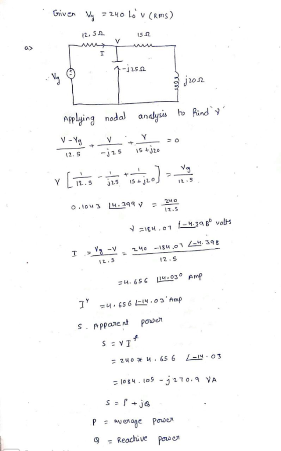
9) The voltage V in the frequency-domain circuit shown in Fig. P10.18 is 240/0°V (rms) a)...
Problem 10.17 Constants The current I, in the frequency-domain circuit shown in (Figure 1) is 48...
 Problem 10.17 Constants The current I, in the frequency-domain circuit shown in (Figure 1) is 48 20° mA (rms). Figure 1 of 1 5() Ω j50 Ω 25 Ω eb923d80b761 180ae7361d64# 10001 s I Fall 18 Faisa art A ind the average power for the current source. Use positive value if the power is absorbed and negative value if the power is delivere Express your answer to three significant figures and include the appropriate units. P31993.675 W Submit X incorrect;...
Problem 3: The line-to-neutral voltage at the terminals of the balanced three-phase load in the circuit...
 Problem 3: The line-to-neutral voltage at the terminals of the balanced three-phase load in the circuit shown in Fig. 3 is 1200V. At this voltage, the load is absorbing 500kVA at 0.96 pf lag. a) Use Van as the reference and express Ina in the polar form. b) Calculate the complex power associated with the ideal three-phase source. c) Check that the total average power delivered equals the total average power absorbed. d) Check that the total magnetizing reactive power...
20Ω 30 Ω j20Ω Fig. 1.7 In the circuit of Fig. 1.8, find the RMS phasor...
 20Ω 30 Ω j20Ω Fig. 1.7 In the circuit of Fig. 1.8, find the RMS phasor voltage V so that the 60 Ω resistor absorbs an average power of 240 W. Hence, determine the complex power delivered to each component, the complex power and the power factor delivered by voltage source. Fig. 1.8 2) P1.8
A three-phase line, which has an impedance of (2 + j4) Ω per phase, feeds two...
A three-phase line, which has an impedance of (2 + j4) Ω per phase, feeds two balanced three-phase loads that are connected in parallel. One of the loads is Y- connected with an impedance of (30 + j40) Ω per phase, and the other is delta- connected with an impedance of (60 + j45) Ω per phase. The line is energized at the sending end from a 60-Hz, three phase, balanced voltage source of 120√3 V (rms, line- to-line). Determine...
In an RLC series circuit, the source has a potential difference of 160 V (rms). The...
In an RLC series circuit, the source has a potential difference of 160 V (rms). The impedance is 175 Ω and the resistance is 40 Ω . Find: a) the average power delivered by the source; P = W b) the power factor;
A balanced three-phase source with a 208 V rms (line-to-line) is delivering power to a balanced...
A balanced three-phase source with a 208 V rms (line-to-line) is delivering power to a balanced Y-connected load with phase impedance Z1 = 4 + j 3 Ohms in parallel with a balanced delta-connected load with phase impedance Z2 = 7.5 + j 6 Ohms. Calculate the active (real) and reactive (imaginary) powers delivered by the source. Draw the power triangle. What is the power factor of the combined load?
0 P10.01 c_9ed For the following set of values, calculate P, Q and state whether the...
 0 P10.01 c_9ed For the following set of values, calculate P, Q and state whether the circuit inside the box is absorbing or delivering (1) average power and (2) magnetizing vars c) v 400 cos(ot30°) V i- 10 sin(ot + 240°) A P-1-1000 w 1 Delivering ▼ Watts o-[ 1732.05 )X VARs Delivering ARs Check
a. The value of the voltage source and all the load impedances of AC circuit in...
 a. The value of the voltage source and all the load impedances of AC circuit in Figure Q2(a) are given as list below; 21 Z3 V. Z2 ZA Figure Q2(a) Calculate the real and reactive power absorbed by load impedances and (C01: P01 - 8 marks) ii. Determine the power factor at the load impedance, (C01: P01 - 2 marks) a. The value of the voltage source and all the load impedances of AC circuit in Figure Q2(a) are given...
12. A sinusoidal voltage Δv = (75.0 V)sin(120t) is applied to a series RLC circuit with...
12. A sinusoidal voltage Δv = (75.0 V)sin(120t) is applied to a series RLC circuit with L = 20.0 mH, C = 130.0 μF, and R = 32.0 Ω. (a) What is the impedance of the circuit? Ω (b) What is the maximum current in the circuit? A 11.An AC power source has an rms voltage of 120 V and operates at a frequency of 60.0 Hz. If a purely inductive circuit is made from the power source and a...
An AC voltage of the form Δν = (85.0 V)sin(330t) is applied to a series RLC...
 An AC voltage of the form Δν = (85.0 V)sin(330t) is applied to a series RLC circuit. If R = 56.0 Ω, C = 28.0,F, and L = 0.300 H, find the following (a) impedance of the circuit (b) rms current in the circuit (c) average power delivered to the circuit
 Problem 10.17 Constants The current I, in the frequency-domain circuit shown in (Figure 1) is 48 20° mA (rms). Figure 1 of 1 5() Ω j50 Ω 25 Ω eb923d80b761 180ae7361d64# 10001 s I Fall 18 Faisa art A ind the average power for the current source. Use positive value if the power is absorbed and negative value if the power is delivere Express your answer to three significant figures and include the appropriate units. P31993.675 W Submit X incorrect;...
 Problem 3: The line-to-neutral voltage at the terminals of the balanced three-phase load in the circuit shown in Fig. 3 is 1200V. At this voltage, the load is absorbing 500kVA at 0.96 pf lag. a) Use Van as the reference and express Ina in the polar form. b) Calculate the complex power associated with the ideal three-phase source. c) Check that the total average power delivered equals the total average power absorbed. d) Check that the total magnetizing reactive power...
 20Ω 30 Ω j20Ω Fig. 1.7 In the circuit of Fig. 1.8, find the RMS phasor voltage V so that the 60 Ω resistor absorbs an average power of 240 W. Hence, determine the complex power delivered to each component, the complex power and the power factor delivered by voltage source. Fig. 1.8 2) P1.8
 0 P10.01 c_9ed For the following set of values, calculate P, Q and state whether the circuit inside the box is absorbing or delivering (1) average power and (2) magnetizing vars c) v 400 cos(ot30°) V i- 10 sin(ot + 240°) A P-1-1000 w 1 Delivering ▼ Watts o-[ 1732.05 )X VARs Delivering ARs Check
 a. The value of the voltage source and all the load impedances of AC circuit in Figure Q2(a) are given as list below; 21 Z3 V. Z2 ZA Figure Q2(a) Calculate the real and reactive power absorbed by load impedances and (C01: P01 - 8 marks) ii. Determine the power factor at the load impedance, (C01: P01 - 2 marks) a. The value of the voltage source and all the load impedances of AC circuit in Figure Q2(a) are given...
 An AC voltage of the form Δν = (85.0 V)sin(330t) is applied to a series RLC circuit. If R = 56.0 Ω, C = 28.0,F, and L = 0.300 H, find the following (a) impedance of the circuit (b) rms current in the circuit (c) average power delivered to the circuit
Most questions answered within 3 hours.
-
You are attempting to calculate a firm’s free cash flow to
equity. You know the following...
asked 25 minutes ago -
the following reaction occurs in a balloon containing
N2O2 gas
N2O4(g)=2NO2(g)
will the volume of the...
asked 1 hour ago -
answer the questions throughout this program
public class Day implements Comparable {
Private Boolean atWork;...
asked 1 hour ago -
This is C++ code for parking fee management program
#include <iostream>
#include <iomanip>
using namespace std;...
asked 1 hour ago -
The free energy change for the following reaction at 25 °C, when
[Sn2+] = 1.17 M...
asked 3 hours ago -
An MNE is this kind of industry when competition in one country
is essentially independent of...
asked 4 hours ago -
. For this set of questions, determine what
proportion of a normal distribution is located betweeneach...
asked 5 hours ago -
A college student is employed as a door-to-door newspaper
salesman. Historical data suggests that the student...
asked 6 hours ago -
MATLAB HW 11 problem using Switch Case and Input commands
Write a script file that calculates...
asked 5 hours ago -
Considering gravitational time dilation, calculate the time that
passes in Earth’s surface while 1 hour passes...
asked 6 hours ago -
Minitab Problem: Take the Lake Hume June rainfall data and find
use the processes outlined in...
asked 7 hours ago -
X Company is trying to decide whether to continue using old
equipment to make Product A...
asked 7 hours ago