![Question 2: [18] 2.1: 2.1.1: Negative feedback in signal amplifiers are utilized to improve distortion and to enhance the fre](http://img.homeworklib.com/questions/76c46170-43ca-11eb-b685-135e22200661.png?x-oss-process=image/resize,w_560)
Homework Answers
Add Answer to:
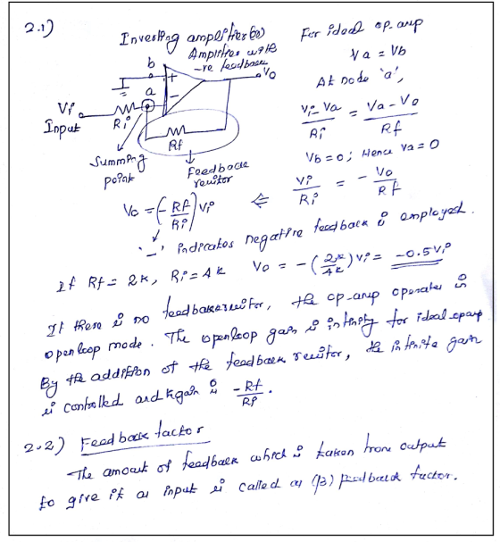
Question 2: [18] 2.1: 2.1.1: Negative feedback in signal amplifiers are utilized to improve distortion and...
1. The feedback is negative. True or False? 2. Find the value of the forward amplifier...
 1. The feedback is negative. True or
False?
2. Find the value of the forward amplifier gain
3. If R1=10kΩ, what value should R2 have to have a feedback
factor of 1/2?
4. The closed-loop gain is about …
(Hint: The closed-loop gain is positive)
A) 1.5
B) 2.8
C) 1.9
D) 3.7
5) If the overall forward amplifier has a 150 Hz bandwidth (due
to a single dominant pole), the bandwidth of the closed-loop
circuit would be around …...
1. The feedback is negative. True or
False?
2. Find the value of the forward amplifier gain
3. If R1=10kΩ, what value should R2 have to have a feedback
factor of 1/2?
4. The closed-loop gain is about …
(Hint: The closed-loop gain is positive)
A) 1.5
B) 2.8
C) 1.9
D) 3.7
5) If the overall forward amplifier has a 150 Hz bandwidth (due
to a single dominant pole), the bandwidth of the closed-loop
circuit would be around …...
Problem 52: (25 points) Operational amplifiers are important building blocks in a wide spectrum of electronic systems such as amplifiers and filters. The concept of feedback control is of central imp...
 Problem 52: (25 points) Operational amplifiers are important building blocks in a wide spectrum of electronic systems such as amplifiers and filters. The concept of feedback control is of central importance in understanding the design of operational amplifier circuits. For without feedback, operational amplifiers behave as comparators. This problem shows why it is necessary to connect the output of an operational amplifier to its inverting input. Negative feedback produces a circuit that is BIBO stable. Figure 1(A) shows the circuit...
ercise 2 Part One: Verify the operation modes of various transistor configurations fask 2.1.1: atermine the...
 ercise 2 Part One: Verify the operation modes of various transistor configurations fask 2.1.1: atermine the input resistance, output resistance, small-signal voltage gain and low-frequency cut-off of the circuits in Figure 2.2, given that gm 3mS for the circuit on the left and 24mS for the circuit on the right. You may assume that CS has been chosen so that its impedance is 'small' at the frequencies of interest. Use simulation to verify your solution. V DD 15 V Voo-12...
Figure 2 shows a feedback amplifier circuit. Rs is the source resistor and R, is the...
 Figure 2 shows a feedback amplifier circuit. Rs is the source resistor and R, is the load resistor RS Vs VI RL OPAMP R2 R1 RM R3 R4 Step 1: open-loop and closed-loop circuits identification 1.1 Identify the source, the load, and the closed-loop amplifier 1.2 Identify the open-loop amplifier (**A" eireuit) and the feedback network (B" eircuit) in the closed-loop amplifier 1.3 Identify the connection type between the "A" circuit and the "B" circuit at both the input and...
Vout should be a sinusoid signal of 12Vp-p Dc voltage to uA741 : +/-8.5V Please simulate...
 Vout should be a sinusoid signal of 12Vp-p
Dc voltage to uA741 : +/-8.5V
Please simulate as well
please help, im completely lost on this
this is all of the information
Experiment 5. RC Sinusoidal Oscillators PURPOSE: This laboratory provides an introduction to the background, analysis and design of sinusoidal oscillators using RC feedback networks and active devices to achieve the criteria for continuous oscillations to occur. EQUIPMENT REQUIRED : 1 Operational amplifier u.A741 1 CEU development station Resistors and...
Vout should be a sinusoid signal of 12Vp-p
Dc voltage to uA741 : +/-8.5V
Please simulate as well
please help, im completely lost on this
this is all of the information
Experiment 5. RC Sinusoidal Oscillators PURPOSE: This laboratory provides an introduction to the background, analysis and design of sinusoidal oscillators using RC feedback networks and active devices to achieve the criteria for continuous oscillations to occur. EQUIPMENT REQUIRED : 1 Operational amplifier u.A741 1 CEU development station Resistors and...
 1. The feedback is negative. True or
False?
2. Find the value of the forward amplifier gain
3. If R1=10kΩ, what value should R2 have to have a feedback
factor of 1/2?
4. The closed-loop gain is about …
(Hint: The closed-loop gain is positive)
A) 1.5
B) 2.8
C) 1.9
D) 3.7
5) If the overall forward amplifier has a 150 Hz bandwidth (due
to a single dominant pole), the bandwidth of the closed-loop
circuit would be around …...
1. The feedback is negative. True or
False?
2. Find the value of the forward amplifier gain
3. If R1=10kΩ, what value should R2 have to have a feedback
factor of 1/2?
4. The closed-loop gain is about …
(Hint: The closed-loop gain is positive)
A) 1.5
B) 2.8
C) 1.9
D) 3.7
5) If the overall forward amplifier has a 150 Hz bandwidth (due
to a single dominant pole), the bandwidth of the closed-loop
circuit would be around …...
 Problem 52: (25 points) Operational amplifiers are important building blocks in a wide spectrum of electronic systems such as amplifiers and filters. The concept of feedback control is of central importance in understanding the design of operational amplifier circuits. For without feedback, operational amplifiers behave as comparators. This problem shows why it is necessary to connect the output of an operational amplifier to its inverting input. Negative feedback produces a circuit that is BIBO stable. Figure 1(A) shows the circuit...
 ercise 2 Part One: Verify the operation modes of various transistor configurations fask 2.1.1: atermine the input resistance, output resistance, small-signal voltage gain and low-frequency cut-off of the circuits in Figure 2.2, given that gm 3mS for the circuit on the left and 24mS for the circuit on the right. You may assume that CS has been chosen so that its impedance is 'small' at the frequencies of interest. Use simulation to verify your solution. V DD 15 V Voo-12...
 Figure 2 shows a feedback amplifier circuit. Rs is the source resistor and R, is the load resistor RS Vs VI RL OPAMP R2 R1 RM R3 R4 Step 1: open-loop and closed-loop circuits identification 1.1 Identify the source, the load, and the closed-loop amplifier 1.2 Identify the open-loop amplifier (**A" eireuit) and the feedback network (B" eircuit) in the closed-loop amplifier 1.3 Identify the connection type between the "A" circuit and the "B" circuit at both the input and...
 Vout should be a sinusoid signal of 12Vp-p
Dc voltage to uA741 : +/-8.5V
Please simulate as well
please help, im completely lost on this
this is all of the information
Experiment 5. RC Sinusoidal Oscillators PURPOSE: This laboratory provides an introduction to the background, analysis and design of sinusoidal oscillators using RC feedback networks and active devices to achieve the criteria for continuous oscillations to occur. EQUIPMENT REQUIRED : 1 Operational amplifier u.A741 1 CEU development station Resistors and...
Vout should be a sinusoid signal of 12Vp-p
Dc voltage to uA741 : +/-8.5V
Please simulate as well
please help, im completely lost on this
this is all of the information
Experiment 5. RC Sinusoidal Oscillators PURPOSE: This laboratory provides an introduction to the background, analysis and design of sinusoidal oscillators using RC feedback networks and active devices to achieve the criteria for continuous oscillations to occur. EQUIPMENT REQUIRED : 1 Operational amplifier u.A741 1 CEU development station Resistors and...
Most questions answered within 3 hours.
-
Hey im just confused about how to put the ' A angle n' and ' S...
asked 14 minutes ago -
Define Diet counceling? What are the
responsibilities of a counselor?
asked 15 minutes ago -
A short essay about the WSJ article on Oreo versus Hydrox.
asked 16 minutes ago -
##8. A program contains the following function definition:
##def cube(num):
##return num * num * num...
asked 23 minutes ago -
find the value z of a standard Normal variable that satisfies
each of the given conditions....
asked 46 minutes ago -
"banana".find('z')
Out[22]: -1
why is this -1
python 3.7
asked 27 minutes ago -
Ilegal Consideration Marna Balin was involved in two automobile
accidents in which she suffered severe injures.She...
asked 36 minutes ago -
Walk through the operation of QuickSort when n = 7 and the input
array is A...
asked 31 minutes ago -
Answer with True or False. Argue the answers
7) The circulation of field B on any...
asked 38 minutes ago -
Chase Co. uses the perpetual inventory method. The inventory
records for Chase reflected the following
Jan...
asked 37 minutes ago -
what are is the correct compression for these two ipv6 ips.. i
keep getting them wrong...
asked 42 minutes ago -
How does the amount of silica gel used change separation?
asked 43 minutes ago