


![LR v3sc =-vlsC+02 C+v2 #+250] (5.11) Equations (5.9. (5.10) and (5.11) may be solved hy elimination and back substitution giv](http://img.homeworklib.com/questions/d7eb6a10-e8e1-11ea-9413-87d837e56500.png?x-oss-process=image/resize,w_560)

Homework Answers
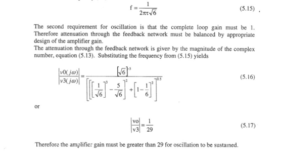
The given circuit are oscillator.
Important points in oscillator by making postive feedback or phase shift 180 degree even without input ac there will be sustained oscillation in the circuit.
Doubt may come with out input how can oscillator produce output waveform actually it takes energy from DC signal given fir biasing and uses it to produce output.
General procedure to solve is to may the phase shift in feedback path as 180 degree.
And then solve by using network analysis and put imaginary part =o to get relation for frequency since at 180 degree phase shift imaginary part is zero.
The frequency is derived in above problem using this criteria only.
Add Answer to:
Vout should be a sinusoid signal of 12Vp-p
Dc voltage to uA741 : +/-8.5V
Please simulate...
(a) Design a inverting Schmitt trigger circuit to be used as a zero crossing detector with transition voltages about ±25...
 (a) Design a inverting Schmitt trigger circuit
to be used as a zero crossing detector with transition voltages
about ±25 mV. Assume the saturation voltages for the op–amp are ±13
V. Draw the voltage transfer characteristic (VTC), i.e., vout vs.
vin.
(b) Design an astable multivibrator to produce
a square signal with a frequency of 1 kHz using C=0.01 µF, R1 = 30
kΩ, and R2 = 20 kΩ. Sketch the circuit waveforms (vo, v +, and v −)
assuming...
(a) Design a inverting Schmitt trigger circuit
to be used as a zero crossing detector with transition voltages
about ±25 mV. Assume the saturation voltages for the op–amp are ±13
V. Draw the voltage transfer characteristic (VTC), i.e., vout vs.
vin.
(b) Design an astable multivibrator to produce
a square signal with a frequency of 1 kHz using C=0.01 µF, R1 = 30
kΩ, and R2 = 20 kΩ. Sketch the circuit waveforms (vo, v +, and v −)
assuming...
3- OPERATIONAL-AMPLIFIER Nominating ampliar Voltage Show OW Difference ampliar Wate Date amplizier Close R Vout Voutin...
 3- OPERATIONAL-AMPLIFIER Nominating ampliar Voltage Show OW Difference ampliar Wate Date amplizier Close R Vout Voutin Vout = vin Buffer = Inverting amplifier Dout = (1 + .. Vout V out 1 V2 ERR Vour (, - v3) Differential Amplifier Non-Inverting amplifier 1- Refer to the op amp in Fig. If v; = 0.5 V, calculate: (a) the output voltage Vos (b) the current in the 10-k! resistor. 25k92 10k02 Oo + 6 2. A 741 op amp has an...
1. Find the transfer function Voda)/Vin(a) for the circuit shown in Figure 1 of the lab (where co...
 Please answer number 1
1. Find the transfer function Voda)/Vin(a) for the circuit shown in Figure 1 of the lab (where complex frequency variable s jo can be substituted for ease of analysis.) Calculate values for R and C such that the phase shift between the output and input is zero for an input frequency of 10kHz. What is the amplitude ratio (gain) of the output to the input at this frequency. 2. The RC network in figure 3 of...
Please answer number 1
1. Find the transfer function Voda)/Vin(a) for the circuit shown in Figure 1 of the lab (where complex frequency variable s jo can be substituted for ease of analysis.) Calculate values for R and C such that the phase shift between the output and input is zero for an input frequency of 10kHz. What is the amplitude ratio (gain) of the output to the input at this frequency. 2. The RC network in figure 3 of...
Please solve all parts pf the questions. Please show clear and neat work. Thank you! FEEDBACK AMPLIFIER ANALYSIS β,s/ Sa) Identify the feedback topology being used. Draw the B-network and You must j...
 Please solve all parts pf the questions. Please show clear and
neat work. Thank you!
FEEDBACK AMPLIFIER ANALYSIS β,s/ Sa) Identify the feedback topology being used. Draw the B-network and You must justify or explain find the numerical value for B- your answer for full credit (20 pts) 2 Assume matching transistors with DC bias voltage (or an ac ground) Sb) Draw and fully label the A-circuit (includes loading effects, R & R but NO feedback) p) Sc) Calculate the...
Please solve all parts pf the questions. Please show clear and
neat work. Thank you!
FEEDBACK AMPLIFIER ANALYSIS β,s/ Sa) Identify the feedback topology being used. Draw the B-network and You must justify or explain find the numerical value for B- your answer for full credit (20 pts) 2 Assume matching transistors with DC bias voltage (or an ac ground) Sb) Draw and fully label the A-circuit (includes loading effects, R & R but NO feedback) p) Sc) Calculate the...
Yes, this is one problem. Please solve ALL PARTS. Guaranteed thumbs up for the person who solves it. 3 1. Photodiode...
 Yes, this is one problem. Please solve ALL PARTS. Guaranteed
thumbs up for the person who solves it.
3 1. Photodiode amplifier circuit You are designinga CF photosensor circuit for a light detection and ranging LiDAR) system in autonomous vehicles. The circuit utilizes a transimpedance amplifier to convert low-level RF photodiode current signal to a usable voltage output. It consists of a photodiode, an amplifier, and feedback capacitor/resistor pair as shown in Figure 1. We will derive simple equations to...
Yes, this is one problem. Please solve ALL PARTS. Guaranteed
thumbs up for the person who solves it.
3 1. Photodiode amplifier circuit You are designinga CF photosensor circuit for a light detection and ranging LiDAR) system in autonomous vehicles. The circuit utilizes a transimpedance amplifier to convert low-level RF photodiode current signal to a usable voltage output. It consists of a photodiode, an amplifier, and feedback capacitor/resistor pair as shown in Figure 1. We will derive simple equations to...
please answer all spring 2019 Name 19. Gain Margin (dB) is: e1OdByb) 15dBa c) 20 d8;...
 please answer all
spring 2019 Name 19. Gain Margin (dB) is: e1OdByb) 15dBa c) 20 d8; d) 35dB; e) 45d8 20. Phase margin (degree) is close to: a) 0; b) 45pe90) 135) e) 180 21. A MOSFET transistor gm 2m5, Cgs 2pF, Ced 0.5pF, its cut-off frequency, ft, is close to: a) 100 b) 300MHz ) 60OMH)1GHe) SGH 22. The cut-off frequency of a BIT with gm-40m5, r pi-2.5Kohm, r o-20Kohm, c mu 1pF and c pi is close to:...
please answer all
spring 2019 Name 19. Gain Margin (dB) is: e1OdByb) 15dBa c) 20 d8; d) 35dB; e) 45d8 20. Phase margin (degree) is close to: a) 0; b) 45pe90) 135) e) 180 21. A MOSFET transistor gm 2m5, Cgs 2pF, Ced 0.5pF, its cut-off frequency, ft, is close to: a) 100 b) 300MHz ) 60OMH)1GHe) SGH 22. The cut-off frequency of a BIT with gm-40m5, r pi-2.5Kohm, r o-20Kohm, c mu 1pF and c pi is close to:...
Laboratory 1: operation amplifier characteristics A. Objectives: 1. To study the basic characteri...
 thanks
Laboratory 1: operation amplifier characteristics A. Objectives: 1. To study the basic characteristics of an operational amplifier 2. To study the bias circuit of an operational amplifier B. Apparatus: 1. DC Power supply 2. Experimental board and corresponding components 3. Electronic calculator (prepared by students) 4. Digital camera (prepared by students for photo taking of the experimental results) 5. Laptop computer with the software PicoScope 6 and Microsoft Word installed. 6. PicoScope PC Oscilloscope and its accessories. 7. Multimeter...
thanks
Laboratory 1: operation amplifier characteristics A. Objectives: 1. To study the basic characteristics of an operational amplifier 2. To study the bias circuit of an operational amplifier B. Apparatus: 1. DC Power supply 2. Experimental board and corresponding components 3. Electronic calculator (prepared by students) 4. Digital camera (prepared by students for photo taking of the experimental results) 5. Laptop computer with the software PicoScope 6 and Microsoft Word installed. 6. PicoScope PC Oscilloscope and its accessories. 7. Multimeter...
 (a) Design a inverting Schmitt trigger circuit
to be used as a zero crossing detector with transition voltages
about ±25 mV. Assume the saturation voltages for the op–amp are ±13
V. Draw the voltage transfer characteristic (VTC), i.e., vout vs.
vin.
(b) Design an astable multivibrator to produce
a square signal with a frequency of 1 kHz using C=0.01 µF, R1 = 30
kΩ, and R2 = 20 kΩ. Sketch the circuit waveforms (vo, v +, and v −)
assuming...
(a) Design a inverting Schmitt trigger circuit
to be used as a zero crossing detector with transition voltages
about ±25 mV. Assume the saturation voltages for the op–amp are ±13
V. Draw the voltage transfer characteristic (VTC), i.e., vout vs.
vin.
(b) Design an astable multivibrator to produce
a square signal with a frequency of 1 kHz using C=0.01 µF, R1 = 30
kΩ, and R2 = 20 kΩ. Sketch the circuit waveforms (vo, v +, and v −)
assuming...
 3- OPERATIONAL-AMPLIFIER Nominating ampliar Voltage Show OW Difference ampliar Wate Date amplizier Close R Vout Voutin Vout = vin Buffer = Inverting amplifier Dout = (1 + .. Vout V out 1 V2 ERR Vour (, - v3) Differential Amplifier Non-Inverting amplifier 1- Refer to the op amp in Fig. If v; = 0.5 V, calculate: (a) the output voltage Vos (b) the current in the 10-k! resistor. 25k92 10k02 Oo + 6 2. A 741 op amp has an...
 Please answer number 1
1. Find the transfer function Voda)/Vin(a) for the circuit shown in Figure 1 of the lab (where complex frequency variable s jo can be substituted for ease of analysis.) Calculate values for R and C such that the phase shift between the output and input is zero for an input frequency of 10kHz. What is the amplitude ratio (gain) of the output to the input at this frequency. 2. The RC network in figure 3 of...
Please answer number 1
1. Find the transfer function Voda)/Vin(a) for the circuit shown in Figure 1 of the lab (where complex frequency variable s jo can be substituted for ease of analysis.) Calculate values for R and C such that the phase shift between the output and input is zero for an input frequency of 10kHz. What is the amplitude ratio (gain) of the output to the input at this frequency. 2. The RC network in figure 3 of...
 Please solve all parts pf the questions. Please show clear and
neat work. Thank you!
FEEDBACK AMPLIFIER ANALYSIS β,s/ Sa) Identify the feedback topology being used. Draw the B-network and You must justify or explain find the numerical value for B- your answer for full credit (20 pts) 2 Assume matching transistors with DC bias voltage (or an ac ground) Sb) Draw and fully label the A-circuit (includes loading effects, R & R but NO feedback) p) Sc) Calculate the...
Please solve all parts pf the questions. Please show clear and
neat work. Thank you!
FEEDBACK AMPLIFIER ANALYSIS β,s/ Sa) Identify the feedback topology being used. Draw the B-network and You must justify or explain find the numerical value for B- your answer for full credit (20 pts) 2 Assume matching transistors with DC bias voltage (or an ac ground) Sb) Draw and fully label the A-circuit (includes loading effects, R & R but NO feedback) p) Sc) Calculate the...
 Yes, this is one problem. Please solve ALL PARTS. Guaranteed
thumbs up for the person who solves it.
3 1. Photodiode amplifier circuit You are designinga CF photosensor circuit for a light detection and ranging LiDAR) system in autonomous vehicles. The circuit utilizes a transimpedance amplifier to convert low-level RF photodiode current signal to a usable voltage output. It consists of a photodiode, an amplifier, and feedback capacitor/resistor pair as shown in Figure 1. We will derive simple equations to...
Yes, this is one problem. Please solve ALL PARTS. Guaranteed
thumbs up for the person who solves it.
3 1. Photodiode amplifier circuit You are designinga CF photosensor circuit for a light detection and ranging LiDAR) system in autonomous vehicles. The circuit utilizes a transimpedance amplifier to convert low-level RF photodiode current signal to a usable voltage output. It consists of a photodiode, an amplifier, and feedback capacitor/resistor pair as shown in Figure 1. We will derive simple equations to...
 please answer all
spring 2019 Name 19. Gain Margin (dB) is: e1OdByb) 15dBa c) 20 d8; d) 35dB; e) 45d8 20. Phase margin (degree) is close to: a) 0; b) 45pe90) 135) e) 180 21. A MOSFET transistor gm 2m5, Cgs 2pF, Ced 0.5pF, its cut-off frequency, ft, is close to: a) 100 b) 300MHz ) 60OMH)1GHe) SGH 22. The cut-off frequency of a BIT with gm-40m5, r pi-2.5Kohm, r o-20Kohm, c mu 1pF and c pi is close to:...
please answer all
spring 2019 Name 19. Gain Margin (dB) is: e1OdByb) 15dBa c) 20 d8; d) 35dB; e) 45d8 20. Phase margin (degree) is close to: a) 0; b) 45pe90) 135) e) 180 21. A MOSFET transistor gm 2m5, Cgs 2pF, Ced 0.5pF, its cut-off frequency, ft, is close to: a) 100 b) 300MHz ) 60OMH)1GHe) SGH 22. The cut-off frequency of a BIT with gm-40m5, r pi-2.5Kohm, r o-20Kohm, c mu 1pF and c pi is close to:...
 thanks
Laboratory 1: operation amplifier characteristics A. Objectives: 1. To study the basic characteristics of an operational amplifier 2. To study the bias circuit of an operational amplifier B. Apparatus: 1. DC Power supply 2. Experimental board and corresponding components 3. Electronic calculator (prepared by students) 4. Digital camera (prepared by students for photo taking of the experimental results) 5. Laptop computer with the software PicoScope 6 and Microsoft Word installed. 6. PicoScope PC Oscilloscope and its accessories. 7. Multimeter...
thanks
Laboratory 1: operation amplifier characteristics A. Objectives: 1. To study the basic characteristics of an operational amplifier 2. To study the bias circuit of an operational amplifier B. Apparatus: 1. DC Power supply 2. Experimental board and corresponding components 3. Electronic calculator (prepared by students) 4. Digital camera (prepared by students for photo taking of the experimental results) 5. Laptop computer with the software PicoScope 6 and Microsoft Word installed. 6. PicoScope PC Oscilloscope and its accessories. 7. Multimeter...
Most questions answered within 3 hours.
-
At the beginning of the period, the Fabricating Department
budgeted direct labor of $136,500 and equipment...
asked 8 minutes ago -
Please answer all
____ 28. Rent control is usually
justified on the grounds that it protects...
asked 7 minutes ago -
PARTS A-D HAVE BEEN ANSWERED. WAS TOLD TO REPOST. ONLY ANSWER
PARTS E and F.
A...
asked 25 minutes ago -
2) You are given the task of finding a representation for a
circle in a drawing...
asked 1 hour ago -
STUDY QUESTION: Does use of diet drug fen-phen
(fenfluramine-phentermine) cause valvular heart disease?
HINT: Valvular heart...
asked 1 hour ago -
1. An object weighing 40 N rests on a surface. The coefficient
of friction is 0.35....
asked 2 hours ago -
Investor company owns 35% of investee company voting stock and
accounts for the investment under the...
asked 3 hours ago -
The number of major faults on a randomly chosen 1 km stretch of
highway has a...
asked 4 hours ago -
Consider the competitive environment of Starbuck's, Progressive
Insurance, a manufacturing firm with low turnover, or a...
asked 4 hours ago -
3. Gains from trade
Consider two neighbouring island countries called Euphoria and
Contente. They each have...
asked 6 hours ago -
A business executive has the option to invest money in two
plans: Plan A guarantees that...
asked 9 hours ago -
Hello, can someone please help me answer this question?
How much heat is absorbed by a...
asked 9 hours ago