

Homework Answers
I have simulated the full wave rectifier first and then added the smoothing circuit so that you can see the difference between the two. Also I have used 1N5818 diodes for simulation, diodes from lab are commonly these only or similar to these.
Output of full wave rectifier
![17 LTspice XVII - [Draft10.raw] Eile View Plot Settings Simulation Tools Window Help DE TOQQ1037% Draft 10.asc k Draft10.raw](http://img.homeworklib.com/questions/cda1d5a0-537a-11eb-b680-29d9ba43d5aa.png?x-oss-process=image/resize,w_560)
As you can see in picture due to non idealities some gap is there between which practical diodes have not yet reached forward bias stage.
Now for smoothening circuit.
Here is the picture of schematic as drawn in LTspice

The smoothing circuit is the capacitor in parallel with a resistor.
The capacitor is charged to the peak voltage but can not discharge till the next cycle repeats thus staying near the peak voltage and discharging very low.
Here the values of capaitor and resistance are so selected that,
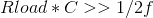
where f is frequency i.e 60Hz.
I have used a capacitor of 100u and resistance that i used is 5.6k.
With these i was able to get a peak of 4.6V and ripple frequency of 119Hz with ripple fluctuations between 4.6V and 4.5V so the output fluctuates by 0.1V.
Here is the netlist code of LTspice for your ease,
* C:\Users\hp\Documents\LTspiceXVII\Draft10.asc
D1 Vb N002 1N5818
D2 Vb N001 1N5818
D3 N002 Va 1N5818
D4 N001 Va 1N5818
V1 N001 0 SINE(0 2.5 60 0 0 0 60)
R1 Vb Va 5.6k
V2 N002 0 SINE(0 -2.5 60 0 0 0 60)
C1 Va Vb 100µ
R2 Va Vb 5.6k
.model D D
.lib C:\Users\hp\Documents\LTspiceXVII\lib\cmp\standard.dio
.tran 0 600ms 500ms
.backanno
.end
transient analysis (between 500ms and 600ms)
with Voltage range between 0 and 5V
![17 LTspice XVII - [Draft10.raw] Eile View Plot Settings Simulation Tools Window Help DE TOQQ1037% Draft 10.asc Draft 10.raw 9](http://img.homeworklib.com/questions/ce99b510-537a-11eb-aebc-952ecdd44960.png?x-oss-process=image/resize,w_560)
To see the ripples more clearly
![17 LTspice XVII - [Draft10.raw] Eile View Plot Settings Simulation Tools Window Help 0 7 O QQA037 % É A SLQ 3 ÝD E E Aa.gr Dr](http://img.homeworklib.com/questions/ceff8cc0-537a-11eb-98be-9377071ac9fd.png?x-oss-process=image/resize,w_560) Here you can see how small the ripples are only between 4,5 and
4.6V on the y-axis of the above graph.
Here you can see how small the ripples are only between 4,5 and
4.6V on the y-axis of the above graph.
Add Answer to:
Resistors Capacitors 5.6k 2, 6.8K2, 8.2k2, 10k12, 12k2, 15k, 18k, 10nF, 15F, 22nF, 33nF, 22k2, 27k...
Resistors 2700 3300 3900 4700 56002 Capacitors 1.OnF 1.5nF 2.2nF Inductors 2.7mH 1500 1800 2200 6800...
 Resistors 2700 3300 3900 4700 56002 Capacitors 1.OnF 1.5nF 2.2nF Inductors 2.7mH 1500 1800 2200 6800 8200 1.0kn 1.2k2 1.5k 1.8k 22.2k02 2.7k 2 3.3nF 4.7nF 6.8nF 3.3k 3.9k 4.7kn 5.6k 26.8k0 8.2k210k 2 12kΩ 10nF 15F 22nF 15kΩ 18kQ2 22kΩ 27kg 33kg 39k 47kg 56kΩ 33nF 47nF 68nF 68k 82kg 100k 120ko 150k 150k 180k 220ko 100nF 150nF 270kn 330kn 390kW 470kn 560kn 680k0 820ko 1.0M Table 1 In this lab, you will design and build Passive & Active...
please answer these 2 questions please i really need help with them for review thank you...
 please answer these 2 questions please i really need
help with them for review thank you so much for your help a quick
response will be greatly appreciated as i am studying now and have
a test tomorrow thank you so much
7. A fixed input voltage, variable load resistance, Zener diode regulator circuit has the following known values: Vi = 20.7V, Vz = 7.5V, PzM = 300mW Calculate the series resistance required if a load resistance of 4700 causes...
please answer these 2 questions please i really need
help with them for review thank you so much for your help a quick
response will be greatly appreciated as i am studying now and have
a test tomorrow thank you so much
7. A fixed input voltage, variable load resistance, Zener diode regulator circuit has the following known values: Vi = 20.7V, Vz = 7.5V, PzM = 300mW Calculate the series resistance required if a load resistance of 4700 causes...
 Resistors 2700 3300 3900 4700 56002 Capacitors 1.OnF 1.5nF 2.2nF Inductors 2.7mH 1500 1800 2200 6800 8200 1.0kn 1.2k2 1.5k 1.8k 22.2k02 2.7k 2 3.3nF 4.7nF 6.8nF 3.3k 3.9k 4.7kn 5.6k 26.8k0 8.2k210k 2 12kΩ 10nF 15F 22nF 15kΩ 18kQ2 22kΩ 27kg 33kg 39k 47kg 56kΩ 33nF 47nF 68nF 68k 82kg 100k 120ko 150k 150k 180k 220ko 100nF 150nF 270kn 330kn 390kW 470kn 560kn 680k0 820ko 1.0M Table 1 In this lab, you will design and build Passive & Active...
 please answer these 2 questions please i really need
help with them for review thank you so much for your help a quick
response will be greatly appreciated as i am studying now and have
a test tomorrow thank you so much
7. A fixed input voltage, variable load resistance, Zener diode regulator circuit has the following known values: Vi = 20.7V, Vz = 7.5V, PzM = 300mW Calculate the series resistance required if a load resistance of 4700 causes...
please answer these 2 questions please i really need
help with them for review thank you so much for your help a quick
response will be greatly appreciated as i am studying now and have
a test tomorrow thank you so much
7. A fixed input voltage, variable load resistance, Zener diode regulator circuit has the following known values: Vi = 20.7V, Vz = 7.5V, PzM = 300mW Calculate the series resistance required if a load resistance of 4700 causes...
Most questions answered within 3 hours.
-
A researcher conducts an experiment comparing three treatment
conditions. The data consist of n = 34...
asked 12 minutes ago -
A generating station is producing 1.8 x 10⁶ W of power that is
to be sent...
asked 3 minutes ago -
Consider the reaction Mg(s)+Fe2+(aq)→Mg2+(aq)+Fe(s) at 49 ∘C ,
where [Fe2+]= 3.30 M and [Mg2+]= 0.210 M...
asked 3 minutes ago -
Of men aged 65 and over 20.5% are still in the US labor force. A
random...
asked 20 minutes ago -
A bag contains 80 balls numbered 1, . . . , 80. Before the game
starts,...
asked 47 minutes ago -
2)Calculate the molar mass of an unknown gas with a mass of
0.462 grams that occupies...
asked 35 minutes ago -
The solubility of lead sulphate, PbSO4, is 4.25 x
10-3 g per 100 mL of solution....
asked 39 minutes ago -
Which one of the following aqueous solutions will have a pH of
0.00 at 25 °C?...
asked 40 minutes ago -
Suppose the market for coffee, a price-taker market and a
constant-cost industry, is initially in long-run...
asked 31 minutes ago -
Yan Yan Corp. has a $4,000 par value bond outstanding with a
coupon rate of 4.9...
asked 41 minutes ago -
Do you think AI is a concern for US and Global companies in the
near future...
asked 21 minutes ago -
Compare the team process STORMING stage of Blockbuster vs
Netflix
1. Storming (definition): During the storming...
asked 39 minutes ago