
please answer these 2 questions please i really need help with them for review thank you so much for your help a quick response will be greatly appreciated as i am studying now and have a test tomorrow thank you so much
Homework Answers

Add Answer to:
please answer these 2 questions please i really need
help with them for review thank you...
There are two questions but the one I need answered is the second one, which uses...
 There are two questions but the one I need answered is the
second one, which uses the first one as reference.
1. Design a zener shunt regulator to provide a regulated voltage of about 10V. You can use a zener diode of type 1N4740 (such as the 1N4740A-ND sold at digikey.com) A voltage supply Vs with a nominal value of 20V 25% is available. The regulator is required to supply a load current of 0 mA to 20 mA. Design...
There are two questions but the one I need answered is the
second one, which uses the first one as reference.
1. Design a zener shunt regulator to provide a regulated voltage of about 10V. You can use a zener diode of type 1N4740 (such as the 1N4740A-ND sold at digikey.com) A voltage supply Vs with a nominal value of 20V 25% is available. The regulator is required to supply a load current of 0 mA to 20 mA. Design...
Answer all the questions, please. 1) 2) In the circuit below, if VB1 = 1.3V and...
 Answer all the questions, please.
1)
2)
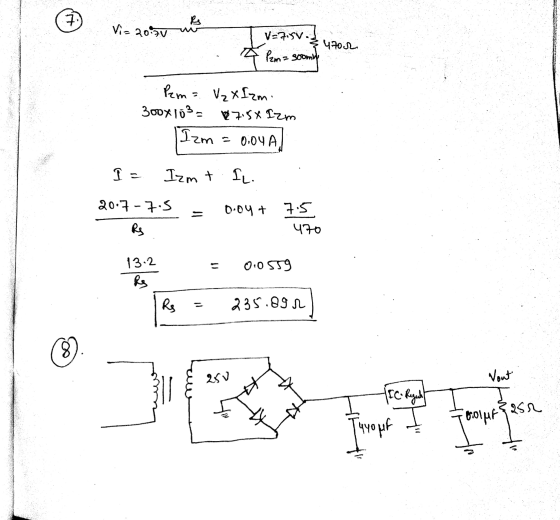
In the circuit below, if VB1 = 1.3V and VB2 = 2.3V, what is the maximum possible value of the output voltage v? Assume a drop of 0.7V across the diodes when forward-biased. Enter your answer in volts. DÝ D2 VBI = Von The circuit below shows a linear regulator. Assume the unregulated input voltage is Vin = 18 V, the Zener specs are (Vz = 5.1 V. Iz = 50 mA), R1...
Answer all the questions, please.
1)
2)
In the circuit below, if VB1 = 1.3V and VB2 = 2.3V, what is the maximum possible value of the output voltage v? Assume a drop of 0.7V across the diodes when forward-biased. Enter your answer in volts. DÝ D2 VBI = Von The circuit below shows a linear regulator. Assume the unregulated input voltage is Vin = 18 V, the Zener specs are (Vz = 5.1 V. Iz = 50 mA), R1...
You need to design a DC power supply that provides an average DC output voltage of...
 You need to design a DC power supply that provides an average DC output voltage of 5V to charge your cellphone. The maximum allowed ripple at the output is ±200 mV. Your cellphone can be modeled as a 1 50Ω load. You have to use a bridge rectifier with four diodes. Note: For calculations, consider constant voltage drop model of the diode with V0 = 0.7V. (a) The charger is designed to use in the US, i.e. transformer primary is...
Design a FULL WAVE BRIDGE RECTIFIER circuit that will: Take 120volts ac, 60 hz, sinusoidal waveform...
 Design a FULL WAVE BRIDGE RECTIFIER circuit that will:
Take 120volts ac, 60 hz, sinusoidal waveform and convert
it to a “regulated “dc value
giving 12 volts +, - 1 volt across a 2000-ohm output
load resistor with no more than 2%
ripple voltage.
You may assume:
a. An ideal power transformer as discussed in class.
b. For hand computations, you must assume a diode given by
Figure 4.8 page 185.
c. A filter capacitor sized per the textbook equation...
Design a FULL WAVE BRIDGE RECTIFIER circuit that will:
Take 120volts ac, 60 hz, sinusoidal waveform and convert
it to a “regulated “dc value
giving 12 volts +, - 1 volt across a 2000-ohm output
load resistor with no more than 2%
ripple voltage.
You may assume:
a. An ideal power transformer as discussed in class.
b. For hand computations, you must assume a diode given by
Figure 4.8 page 185.
c. A filter capacitor sized per the textbook equation...
Please answer all the questions, thank you! It is a important homework for me! I will...
 Please answer all the questions, thank you! It is a important
homework for me! I will like you answer if correct!
For the questions on this page, assume that that an induction motor is rated to deliver 10kW (approximately 13.3HP} when operated at 240VRMS 60Hz. The motor has a lagging power factor of 0.8. The building electrical service only supplies 208VRMs, so the motor can not be connected directly to the electric service. An ideal transformer is used to create...
Please answer all the questions, thank you! It is a important
homework for me! I will like you answer if correct!
For the questions on this page, assume that that an induction motor is rated to deliver 10kW (approximately 13.3HP} when operated at 240VRMS 60Hz. The motor has a lagging power factor of 0.8. The building electrical service only supplies 208VRMs, so the motor can not be connected directly to the electric service. An ideal transformer is used to create...
Can I please get help with these questions? Thank you in advanced :) Inside a uniform...
 Can
I please get help with these questions? Thank you in advanced
:)
Inside a uniform 0.054-T magnetic field, a beam of electrons moves in a circle with radius 6.2 x 10⁻⁴ m. How fast must the electrons be moving? What is the equivalent resistance of this portion of a circuit? 12 Ω 4 Ω - 3 Ω 6Ω AM 12 Ω A battery is hooked to a series combination of a switch, a resistor, and an initially uncharged capacitor....
Can
I please get help with these questions? Thank you in advanced
:)
Inside a uniform 0.054-T magnetic field, a beam of electrons moves in a circle with radius 6.2 x 10⁻⁴ m. How fast must the electrons be moving? What is the equivalent resistance of this portion of a circuit? 12 Ω 4 Ω - 3 Ω 6Ω AM 12 Ω A battery is hooked to a series combination of a switch, a resistor, and an initially uncharged capacitor....
I really need some help with part a part B and part see if you could...
 I
really need some help with part a part B and part see if you could
please explain how you got the answer that would be great!
Class Management | Help Online HW#7 Begin Date: 2/17/2020 12:01:00 AM - Due Date: 3/9/2020 11:59:00 PM End Date: 5/9/2020 11:59:00 PM (11%) Problem 5: A large power plant generates electricity at 12.0 kV. Its old transformer once converted the voltage to 355 kV. The secondary coil of this transformer is being replaced...
I
really need some help with part a part B and part see if you could
please explain how you got the answer that would be great!
Class Management | Help Online HW#7 Begin Date: 2/17/2020 12:01:00 AM - Due Date: 3/9/2020 11:59:00 PM End Date: 5/9/2020 11:59:00 PM (11%) Problem 5: A large power plant generates electricity at 12.0 kV. Its old transformer once converted the voltage to 355 kV. The secondary coil of this transformer is being replaced...
Accuracy is important. Do not round intermediates and check the answer range to make sure you...
 Accuracy is important. Do not round intermediates and check the
answer range to make sure you are correct.
Values:
[01] 2.08 [02]
68.47 [03] 0.239 [04] 1173.7 [05] 1403. [06] 53.8
THE CORRECT ANSWERS WILL BE IN THE FOLLOWING RANGES:
8-1a. 140, 220 Hz
8-1b. 40:0, 62:0 mA
8-2a. 70:0, 99:0 V
8-2b. 140:0, 160:0 V
8-2c. 60:0, 99:0 V
8-2d. 60:0, 90:0 V
8-3a. 40:0; 99:0 pF
8-3b. 100; 400 mV
8-3c. 1:00; 3:00 mV
8-4a. 100; 150 V...
Accuracy is important. Do not round intermediates and check the
answer range to make sure you are correct.
Values:
[01] 2.08 [02]
68.47 [03] 0.239 [04] 1173.7 [05] 1403. [06] 53.8
THE CORRECT ANSWERS WILL BE IN THE FOLLOWING RANGES:
8-1a. 140, 220 Hz
8-1b. 40:0, 62:0 mA
8-2a. 70:0, 99:0 V
8-2b. 140:0, 160:0 V
8-2c. 60:0, 99:0 V
8-2d. 60:0, 90:0 V
8-3a. 40:0; 99:0 pF
8-3b. 100; 400 mV
8-3c. 1:00; 3:00 mV
8-4a. 100; 150 V...
please help me with these 2 questions please all 2 please i need them please Exercise...
 please help me with these 2 questions please all 2 please i need
them please
Exercise 25.46 14 of 21 Constants Consider the circuit of the figure (Figure 1). Part A 12 resistor? What is the total rate at which electrical energy is dissipated in the 5.0 Express your answer using two significant figures. IVO A20 ? Figure 1 of 1 > Submit Request Answer 1.6 12 16.0V w a b Part B 5.0 12 9.012 1.4 12 8.0V What...
please help me with these 2 questions please all 2 please i need
them please
Exercise 25.46 14 of 21 Constants Consider the circuit of the figure (Figure 1). Part A 12 resistor? What is the total rate at which electrical energy is dissipated in the 5.0 Express your answer using two significant figures. IVO A20 ? Figure 1 of 1 > Submit Request Answer 1.6 12 16.0V w a b Part B 5.0 12 9.012 1.4 12 8.0V What...
Need help with B to D, Thank you!! RLC circuit (2) 5 of 10 > Review...
 Need help with B to D, Thank you!!
RLC circuit (2) 5 of 10 > Review | Constants Learning Goal: To calculate and use complex impedance. A 25.0-9 resistor, 50 mH inductor, and 200 uF capacitor are connected as shown below to an AC voltage source with amplitude 100 V and w=200 5-1. R mat L mm Part A - Impedance of R-C Find the complex impedance of the R-C combination, in . Format: Since Z = R + Xj,...
Need help with B to D, Thank you!!
RLC circuit (2) 5 of 10 > Review | Constants Learning Goal: To calculate and use complex impedance. A 25.0-9 resistor, 50 mH inductor, and 200 uF capacitor are connected as shown below to an AC voltage source with amplitude 100 V and w=200 5-1. R mat L mm Part A - Impedance of R-C Find the complex impedance of the R-C combination, in . Format: Since Z = R + Xj,...
 There are two questions but the one I need answered is the
second one, which uses the first one as reference.
1. Design a zener shunt regulator to provide a regulated voltage of about 10V. You can use a zener diode of type 1N4740 (such as the 1N4740A-ND sold at digikey.com) A voltage supply Vs with a nominal value of 20V 25% is available. The regulator is required to supply a load current of 0 mA to 20 mA. Design...
There are two questions but the one I need answered is the
second one, which uses the first one as reference.
1. Design a zener shunt regulator to provide a regulated voltage of about 10V. You can use a zener diode of type 1N4740 (such as the 1N4740A-ND sold at digikey.com) A voltage supply Vs with a nominal value of 20V 25% is available. The regulator is required to supply a load current of 0 mA to 20 mA. Design...
 Answer all the questions, please.
1)
2)
In the circuit below, if VB1 = 1.3V and VB2 = 2.3V, what is the maximum possible value of the output voltage v? Assume a drop of 0.7V across the diodes when forward-biased. Enter your answer in volts. DÝ D2 VBI = Von The circuit below shows a linear regulator. Assume the unregulated input voltage is Vin = 18 V, the Zener specs are (Vz = 5.1 V. Iz = 50 mA), R1...
Answer all the questions, please.
1)
2)
In the circuit below, if VB1 = 1.3V and VB2 = 2.3V, what is the maximum possible value of the output voltage v? Assume a drop of 0.7V across the diodes when forward-biased. Enter your answer in volts. DÝ D2 VBI = Von The circuit below shows a linear regulator. Assume the unregulated input voltage is Vin = 18 V, the Zener specs are (Vz = 5.1 V. Iz = 50 mA), R1...
 You need to design a DC power supply that provides an average DC output voltage of 5V to charge your cellphone. The maximum allowed ripple at the output is ±200 mV. Your cellphone can be modeled as a 1 50Ω load. You have to use a bridge rectifier with four diodes. Note: For calculations, consider constant voltage drop model of the diode with V0 = 0.7V. (a) The charger is designed to use in the US, i.e. transformer primary is...
 Design a FULL WAVE BRIDGE RECTIFIER circuit that will:
Take 120volts ac, 60 hz, sinusoidal waveform and convert
it to a “regulated “dc value
giving 12 volts +, - 1 volt across a 2000-ohm output
load resistor with no more than 2%
ripple voltage.
You may assume:
a. An ideal power transformer as discussed in class.
b. For hand computations, you must assume a diode given by
Figure 4.8 page 185.
c. A filter capacitor sized per the textbook equation...
Design a FULL WAVE BRIDGE RECTIFIER circuit that will:
Take 120volts ac, 60 hz, sinusoidal waveform and convert
it to a “regulated “dc value
giving 12 volts +, - 1 volt across a 2000-ohm output
load resistor with no more than 2%
ripple voltage.
You may assume:
a. An ideal power transformer as discussed in class.
b. For hand computations, you must assume a diode given by
Figure 4.8 page 185.
c. A filter capacitor sized per the textbook equation...
 Please answer all the questions, thank you! It is a important
homework for me! I will like you answer if correct!
For the questions on this page, assume that that an induction motor is rated to deliver 10kW (approximately 13.3HP} when operated at 240VRMS 60Hz. The motor has a lagging power factor of 0.8. The building electrical service only supplies 208VRMs, so the motor can not be connected directly to the electric service. An ideal transformer is used to create...
Please answer all the questions, thank you! It is a important
homework for me! I will like you answer if correct!
For the questions on this page, assume that that an induction motor is rated to deliver 10kW (approximately 13.3HP} when operated at 240VRMS 60Hz. The motor has a lagging power factor of 0.8. The building electrical service only supplies 208VRMs, so the motor can not be connected directly to the electric service. An ideal transformer is used to create...
 Can
I please get help with these questions? Thank you in advanced
:)
Inside a uniform 0.054-T magnetic field, a beam of electrons moves in a circle with radius 6.2 x 10⁻⁴ m. How fast must the electrons be moving? What is the equivalent resistance of this portion of a circuit? 12 Ω 4 Ω - 3 Ω 6Ω AM 12 Ω A battery is hooked to a series combination of a switch, a resistor, and an initially uncharged capacitor....
Can
I please get help with these questions? Thank you in advanced
:)
Inside a uniform 0.054-T magnetic field, a beam of electrons moves in a circle with radius 6.2 x 10⁻⁴ m. How fast must the electrons be moving? What is the equivalent resistance of this portion of a circuit? 12 Ω 4 Ω - 3 Ω 6Ω AM 12 Ω A battery is hooked to a series combination of a switch, a resistor, and an initially uncharged capacitor....
 I
really need some help with part a part B and part see if you could
please explain how you got the answer that would be great!
Class Management | Help Online HW#7 Begin Date: 2/17/2020 12:01:00 AM - Due Date: 3/9/2020 11:59:00 PM End Date: 5/9/2020 11:59:00 PM (11%) Problem 5: A large power plant generates electricity at 12.0 kV. Its old transformer once converted the voltage to 355 kV. The secondary coil of this transformer is being replaced...
I
really need some help with part a part B and part see if you could
please explain how you got the answer that would be great!
Class Management | Help Online HW#7 Begin Date: 2/17/2020 12:01:00 AM - Due Date: 3/9/2020 11:59:00 PM End Date: 5/9/2020 11:59:00 PM (11%) Problem 5: A large power plant generates electricity at 12.0 kV. Its old transformer once converted the voltage to 355 kV. The secondary coil of this transformer is being replaced...
 Accuracy is important. Do not round intermediates and check the
answer range to make sure you are correct.
Values:
[01] 2.08 [02]
68.47 [03] 0.239 [04] 1173.7 [05] 1403. [06] 53.8
THE CORRECT ANSWERS WILL BE IN THE FOLLOWING RANGES:
8-1a. 140, 220 Hz
8-1b. 40:0, 62:0 mA
8-2a. 70:0, 99:0 V
8-2b. 140:0, 160:0 V
8-2c. 60:0, 99:0 V
8-2d. 60:0, 90:0 V
8-3a. 40:0; 99:0 pF
8-3b. 100; 400 mV
8-3c. 1:00; 3:00 mV
8-4a. 100; 150 V...
Accuracy is important. Do not round intermediates and check the
answer range to make sure you are correct.
Values:
[01] 2.08 [02]
68.47 [03] 0.239 [04] 1173.7 [05] 1403. [06] 53.8
THE CORRECT ANSWERS WILL BE IN THE FOLLOWING RANGES:
8-1a. 140, 220 Hz
8-1b. 40:0, 62:0 mA
8-2a. 70:0, 99:0 V
8-2b. 140:0, 160:0 V
8-2c. 60:0, 99:0 V
8-2d. 60:0, 90:0 V
8-3a. 40:0; 99:0 pF
8-3b. 100; 400 mV
8-3c. 1:00; 3:00 mV
8-4a. 100; 150 V...
 please help me with these 2 questions please all 2 please i need
them please
Exercise 25.46 14 of 21 Constants Consider the circuit of the figure (Figure 1). Part A 12 resistor? What is the total rate at which electrical energy is dissipated in the 5.0 Express your answer using two significant figures. IVO A20 ? Figure 1 of 1 > Submit Request Answer 1.6 12 16.0V w a b Part B 5.0 12 9.012 1.4 12 8.0V What...
please help me with these 2 questions please all 2 please i need
them please
Exercise 25.46 14 of 21 Constants Consider the circuit of the figure (Figure 1). Part A 12 resistor? What is the total rate at which electrical energy is dissipated in the 5.0 Express your answer using two significant figures. IVO A20 ? Figure 1 of 1 > Submit Request Answer 1.6 12 16.0V w a b Part B 5.0 12 9.012 1.4 12 8.0V What...
 Need help with B to D, Thank you!!
RLC circuit (2) 5 of 10 > Review | Constants Learning Goal: To calculate and use complex impedance. A 25.0-9 resistor, 50 mH inductor, and 200 uF capacitor are connected as shown below to an AC voltage source with amplitude 100 V and w=200 5-1. R mat L mm Part A - Impedance of R-C Find the complex impedance of the R-C combination, in . Format: Since Z = R + Xj,...
Need help with B to D, Thank you!!
RLC circuit (2) 5 of 10 > Review | Constants Learning Goal: To calculate and use complex impedance. A 25.0-9 resistor, 50 mH inductor, and 200 uF capacitor are connected as shown below to an AC voltage source with amplitude 100 V and w=200 5-1. R mat L mm Part A - Impedance of R-C Find the complex impedance of the R-C combination, in . Format: Since Z = R + Xj,...
Most questions answered within 3 hours.
-
If you’re standing at the bottom of a hill and asked to evaluate
it while being...
asked 35 minutes ago -
1. Which region has taken the lead in the world of
e-waste handling?
a) European Union...
asked 29 minutes ago -
A 8.15- g bullet from a 9-mm pistol has a velocity of 366.0 m/s.
It strikes...
asked 2 hours ago -
The outstanding bonds of Alpha Extracts have a yield to maturity
of 7.4 percent and a...
asked 1 hour ago -
The Problem: The Case of the Harmonizing Vacations
Your CEO is exploring partnering with a European...
asked 3 hours ago -
A chemical equation is balanced by adding coefficients in front
of some formulas so that the...
asked 3 hours ago -
From the literature (reference your sources): What are the
lattice parameters of calcite and aragonite? Why...
asked 4 hours ago -
Your system is rejecting the question am asking which is
preceded by a case study. It...
asked 4 hours ago -
3. On January 2, 2000, Larry creates a trust with himself as
trustee. Larry as trustee...
asked 4 hours ago -
A member of the volleyball team spikes the ball. During this
process, she changes the velocity...
asked 4 hours ago -
Are adult gamers less likely to use a gaming console (Xbox,
PlayStation, Wii, etc...) than teen...
asked 5 hours ago -
The University of
Texas recently reported that 43% of college students aged 18-24
would spend their...
asked 5 hours ago