
Homework Answers
Add Answer to:
Consider the frame and loading shown in the adjoining figure Use the dimensions and load values...
Consider the frame and loading shown in the adjoining figure. Use the dimensions and load values...
 Consider the frame and loading shown in the adjoining figure. Use the dimensions and load values in the table below. Analyse the frame and determine the reactions and internal actions required in the table below. Enter your answers in the space provided. tab- 000000000000000000000UI C Dimensions: 3.3 m 2.5 m 4 m 22m c Loading: w 20 kN/m ] Results: Provide Answer for the followings to an accuracy of 2.5% Absolute Value Unit Direction Reactions Dy Member Forces Shear force...
Consider the frame and loading shown in the adjoining figure. Use the dimensions and load values...
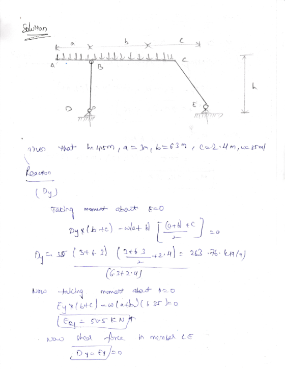
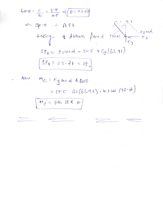
 Consider the frame and loading shown in the adjoining figure.
Use the dimensions and load values in the table below. Analyse the
frame and determine the reactions and internal actions required in
the table below. Enter your answers in the space provided.
Dimensions:
h = 3.8m
a = 2.5m
b = 4.8m
c = 1.8m
w = 20kn/m
Consider the frame and loading shown in the adjoining figure. Use the dimensions and load values in the table below. Analyse the...
Consider the frame and loading shown in the adjoining figure.
Use the dimensions and load values in the table below. Analyse the
frame and determine the reactions and internal actions required in
the table below. Enter your answers in the space provided.
Dimensions:
h = 3.8m
a = 2.5m
b = 4.8m
c = 1.8m
w = 20kn/m
Consider the frame and loading shown in the adjoining figure. Use the dimensions and load values in the table below. Analyse the...
Consider the structure and applied actions shown in the adjoining figure The frame is subjected to...
 Consider the structure and applied actions shown in the adjoining figure The frame is subjected to a uniformly distributed load on CD, a change in temperature in AB and support settlement at D. Use the dimensions and load values in the table below. Analyse the structure for all actions acting applied simultaneously and determine the reactions, member forces and displacement required in the table below. Enter your answers in the space provided. Dimensions 4 m 0.275lm 0.00001 Applied actions: DY...
Use the Moment Distribution Method to analyse the frame when subjected to the loading shown. Dimensions and load values...
 Use the Moment Distribution Method to analyse the frame when subjected to the loading shown. Dimensions and load values, which depend on your student ID, are given in the table below Determine the member forces and support reactions required in the table below Enter your answers in the space provided. Dimensions 5.4 m 2.6 m 6.8 m 3.4 m 280 kN lied actions 285 kN 13 kN/m Provide Answer for the followings to an accuracy of 2.5% sult required Absol...
Consider the pin-jointed truss and applied forces shown in the adjoining figure. Consider the pin-jointed truss...
 Consider the pin-jointed truss and applied forces shown in the
adjoining figure.
Consider the pin-jointed truss and applied forces shown in the adjoining figure Use the dimensions and load values in the table below Analyse the truss and determine the reactions and member forces required in the table below Enter your answers in the space provided Dimensions Applied forces 81.2 kN 125 kN Results Provide Answer for the followings to an accuracy of 2.5% Absolute Value Unit Direction Reactions Member...
Consider the pin-jointed truss and applied forces shown in the
adjoining figure.
Consider the pin-jointed truss and applied forces shown in the adjoining figure Use the dimensions and load values in the table below Analyse the truss and determine the reactions and member forces required in the table below Enter your answers in the space provided Dimensions Applied forces 81.2 kN 125 kN Results Provide Answer for the followings to an accuracy of 2.5% Absolute Value Unit Direction Reactions Member...
Consider the structure and applied actions shown in the adjoining figure. The frame is subjected to...
 Consider the structure and applied actions shown in the adjoining figure. The frame is subjected to a uniformly distributed load on AB, an initial curvature in CD and support settlement at A Use the dimensions and load values in the table below. Analyse the structure for all actions applied simultaneously and determine the reactions, member forces and displacement required in the table below Enter your answers in the space provided.
please answer all the questions P A Consider the pin-jointed truss and applied forces shown in...
 please answer all the questions
P A Consider the pin-jointed truss and applied forces shown in the adjoining figure Use the dimensions and load values in the table below. Analyse the truss and determine the reactions and member forces required in the table below Enter your answers in the space provided. Dimensions: Applied forces: 81.2 kN 112.5kN 5.5m 6.1 m Results: Provide Answer for the followings to an accuracy of 2.5% Absolute Value Unit Direction Reactions Hx- IkN Gx- Member...
please answer all the questions
P A Consider the pin-jointed truss and applied forces shown in the adjoining figure Use the dimensions and load values in the table below. Analyse the truss and determine the reactions and member forces required in the table below Enter your answers in the space provided. Dimensions: Applied forces: 81.2 kN 112.5kN 5.5m 6.1 m Results: Provide Answer for the followings to an accuracy of 2.5% Absolute Value Unit Direction Reactions Hx- IkN Gx- Member...
A) Consider the frame in the adjoining figure, which is subjected to the following actions: Case...
 A) Consider the frame in the adjoining figure, which is subjected to the following actions: Case 1) Distributed load acting on member BC only Case 2) Initial curvature I member CD only Case 3) Support settlement at point D only Determine the horizontal displacement at point B for each of the above cases. B) Consider load case 4 below where all actions act simultaneously Case 4) All actions combined = Cases 1 +2+3 Determine for case 4 the support reactions,...
2. For the beam and loading shown in the following figure: (a) find all the reaction...
 2. For the beam and loading shown in the following figure: (a) find all the reaction forces, (b) draw the shear and bending moment diagrams and (c) determine the maximum absolute value of the shear and the bending moment. 25 kN m 40 kN 401N 0.61 1.S 0.6 m
Use moment distribution method or slope deflection method. The frame shown if Fig. 2.1 is supporting...
 Use moment distribution method or slope deflection
method.
The frame shown if Fig. 2.1 is supporting a lateral load of 60 kN and a gravity load of 50 kNIm. Neglect the weight of the members (a) Determine th reaction forces. (b) Draw the axial, shear, and bending moment and qualitative deflected shape diagrams of the frame. Specify values at a change of loading positions and at all points of zero shear and moment. Use slope-deflection method 2m Fig. 2.1 w...
Use moment distribution method or slope deflection
method.
The frame shown if Fig. 2.1 is supporting a lateral load of 60 kN and a gravity load of 50 kNIm. Neglect the weight of the members (a) Determine th reaction forces. (b) Draw the axial, shear, and bending moment and qualitative deflected shape diagrams of the frame. Specify values at a change of loading positions and at all points of zero shear and moment. Use slope-deflection method 2m Fig. 2.1 w...
 Consider the frame and loading shown in the adjoining figure. Use the dimensions and load values in the table below. Analyse the frame and determine the reactions and internal actions required in the table below. Enter your answers in the space provided. tab- 000000000000000000000UI C Dimensions: 3.3 m 2.5 m 4 m 22m c Loading: w 20 kN/m ] Results: Provide Answer for the followings to an accuracy of 2.5% Absolute Value Unit Direction Reactions Dy Member Forces Shear force...
 Consider the frame and loading shown in the adjoining figure.
Use the dimensions and load values in the table below. Analyse the
frame and determine the reactions and internal actions required in
the table below. Enter your answers in the space provided.
Dimensions:
h = 3.8m
a = 2.5m
b = 4.8m
c = 1.8m
w = 20kn/m
Consider the frame and loading shown in the adjoining figure. Use the dimensions and load values in the table below. Analyse the...
Consider the frame and loading shown in the adjoining figure.
Use the dimensions and load values in the table below. Analyse the
frame and determine the reactions and internal actions required in
the table below. Enter your answers in the space provided.
Dimensions:
h = 3.8m
a = 2.5m
b = 4.8m
c = 1.8m
w = 20kn/m
Consider the frame and loading shown in the adjoining figure. Use the dimensions and load values in the table below. Analyse the...
 Consider the structure and applied actions shown in the adjoining figure The frame is subjected to a uniformly distributed load on CD, a change in temperature in AB and support settlement at D. Use the dimensions and load values in the table below. Analyse the structure for all actions acting applied simultaneously and determine the reactions, member forces and displacement required in the table below. Enter your answers in the space provided. Dimensions 4 m 0.275lm 0.00001 Applied actions: DY...
 Use the Moment Distribution Method to analyse the frame when subjected to the loading shown. Dimensions and load values, which depend on your student ID, are given in the table below Determine the member forces and support reactions required in the table below Enter your answers in the space provided. Dimensions 5.4 m 2.6 m 6.8 m 3.4 m 280 kN lied actions 285 kN 13 kN/m Provide Answer for the followings to an accuracy of 2.5% sult required Absol...
 Consider the pin-jointed truss and applied forces shown in the
adjoining figure.
Consider the pin-jointed truss and applied forces shown in the adjoining figure Use the dimensions and load values in the table below Analyse the truss and determine the reactions and member forces required in the table below Enter your answers in the space provided Dimensions Applied forces 81.2 kN 125 kN Results Provide Answer for the followings to an accuracy of 2.5% Absolute Value Unit Direction Reactions Member...
Consider the pin-jointed truss and applied forces shown in the
adjoining figure.
Consider the pin-jointed truss and applied forces shown in the adjoining figure Use the dimensions and load values in the table below Analyse the truss and determine the reactions and member forces required in the table below Enter your answers in the space provided Dimensions Applied forces 81.2 kN 125 kN Results Provide Answer for the followings to an accuracy of 2.5% Absolute Value Unit Direction Reactions Member...
 Consider the structure and applied actions shown in the adjoining figure. The frame is subjected to a uniformly distributed load on AB, an initial curvature in CD and support settlement at A Use the dimensions and load values in the table below. Analyse the structure for all actions applied simultaneously and determine the reactions, member forces and displacement required in the table below Enter your answers in the space provided.
 please answer all the questions
P A Consider the pin-jointed truss and applied forces shown in the adjoining figure Use the dimensions and load values in the table below. Analyse the truss and determine the reactions and member forces required in the table below Enter your answers in the space provided. Dimensions: Applied forces: 81.2 kN 112.5kN 5.5m 6.1 m Results: Provide Answer for the followings to an accuracy of 2.5% Absolute Value Unit Direction Reactions Hx- IkN Gx- Member...
please answer all the questions
P A Consider the pin-jointed truss and applied forces shown in the adjoining figure Use the dimensions and load values in the table below. Analyse the truss and determine the reactions and member forces required in the table below Enter your answers in the space provided. Dimensions: Applied forces: 81.2 kN 112.5kN 5.5m 6.1 m Results: Provide Answer for the followings to an accuracy of 2.5% Absolute Value Unit Direction Reactions Hx- IkN Gx- Member...
 A) Consider the frame in the adjoining figure, which is subjected to the following actions: Case 1) Distributed load acting on member BC only Case 2) Initial curvature I member CD only Case 3) Support settlement at point D only Determine the horizontal displacement at point B for each of the above cases. B) Consider load case 4 below where all actions act simultaneously Case 4) All actions combined = Cases 1 +2+3 Determine for case 4 the support reactions,...
 2. For the beam and loading shown in the following figure: (a) find all the reaction forces, (b) draw the shear and bending moment diagrams and (c) determine the maximum absolute value of the shear and the bending moment. 25 kN m 40 kN 401N 0.61 1.S 0.6 m
 Use moment distribution method or slope deflection
method.
The frame shown if Fig. 2.1 is supporting a lateral load of 60 kN and a gravity load of 50 kNIm. Neglect the weight of the members (a) Determine th reaction forces. (b) Draw the axial, shear, and bending moment and qualitative deflected shape diagrams of the frame. Specify values at a change of loading positions and at all points of zero shear and moment. Use slope-deflection method 2m Fig. 2.1 w...
Use moment distribution method or slope deflection
method.
The frame shown if Fig. 2.1 is supporting a lateral load of 60 kN and a gravity load of 50 kNIm. Neglect the weight of the members (a) Determine th reaction forces. (b) Draw the axial, shear, and bending moment and qualitative deflected shape diagrams of the frame. Specify values at a change of loading positions and at all points of zero shear and moment. Use slope-deflection method 2m Fig. 2.1 w...
Most questions answered within 3 hours.
-
Calculate the pH of each of the following solutions.
0.50 M HBr
3.1×10⁻⁴ M KOH
4.2×10⁻⁵...
asked 28 minutes ago -
For the year ended December 31, Depot Max’s cost of merchandise
sold was $85,600. Inventory at the...
asked 28 minutes ago -
Week 10 - Professional Memo Assignment
Professional Memo Assignment
Your mission for this week, should you...
asked 32 minutes ago -
Write a Python program that stores the data for each
player on the team, and it...
asked 42 minutes ago -
In
the last 3 months, mike never knows when he is going to get his
allowance...
asked 1 hour ago -
Is Ca(OH)2 a Bronsted base, Lewis base, or both? Why?
asked 57 minutes ago -
1A- Why don’t voters complain about U.S. tariffs on imported
sugar?
Because sugar is only a...
asked 1 hour ago -
Cash Payback Period
Primera Banco is evaluating two capital investment proposals for
a drive-up ATM kiosk,...
asked 1 hour ago -
Create a button in Swift (Xcode) that will create a charge,
create a charge using Stripe's...
asked 1 hour ago -
The reaction rate of CO and NO2 in the reaction
CO(g) + NO2(g) → CO2(g) +...
asked 1 hour ago -
Imagine that a chemist puts 6.40 mol each of
C3H8 and O2 in a 1.00-L container...
asked 1 hour ago -
How much money should be invested today in order to have $8340
at the end of...
asked 1 hour ago