
Homework Answers
Add Answer to:
Q1: A flyback converter has the following circuit parameters: Va = 24V,N1/N2 = 3, Lim =...
Quiz 12 This flyback converter has the following parameters: VS = 5.0 V D = 0.5...
 Quiz 12
This flyback converter has the following parameters:
VS = 5.0 V D = 0.5 N2/N1 = 4
Switching Freq f = 150 kHz
C = 20 µF (micro F) Lm = 50 µH (micro H) R = 50 ?
(Ohms)
The capacitor is not ideal and has an RCesr = 0.4 ?
(Ohms).
The switch is not ideal and has Ron = 2 ? (Ohms).
Run a PSpice simulation with t = 6.0ms:
(a) Find the average output...
Quiz 12
This flyback converter has the following parameters:
VS = 5.0 V D = 0.5 N2/N1 = 4
Switching Freq f = 150 kHz
C = 20 µF (micro F) Lm = 50 µH (micro H) R = 50 ?
(Ohms)
The capacitor is not ideal and has an RCesr = 0.4 ?
(Ohms).
The switch is not ideal and has Ron = 2 ? (Ohms).
Run a PSpice simulation with t = 6.0ms:
(a) Find the average output...
VI 100 L 100 100 1000uF 3 2. The flyback converter shown, operates at 10 kHz....
 VI 100 L 100 100 1000uF 3 2. The flyback converter shown, operates at 10 kHz. The duty ratio of switch closed is D -0.2. The Primary to secondary ratio is 5 to 1 (N /N, -1/5, the load resistance is 15 . Determine: (a) Output voltage. (b) Average, minimum and maximum current in LI - Lm (the magnetizing inductance). (c) The output voltage ripple.
D1 T1 c1 RL 15 3. The flyback converter shown, operates at 250 kHz. The 1 duty ratio ofswitch closed is D = 0.6. Determine: (a) Output voltage. (b) Average, minimum and maximum current in L1 (the mag...
 D1 T1 c1 RL 15 3. The flyback converter shown, operates at 250 kHz. The 1 duty ratio ofswitch closed is D = 0.6. Determine: (a) Output voltage. (b) Average, minimum and maximum current in L1 (the magnetizing inductance.) (c) The output voltage ripple. Ll 1030uF 82
D1 T1 c1 RL 15 3. The flyback converter shown, operates at 250 kHz. The 1 duty ratio ofswitch closed is D = 0.6. Determine: (a) Output voltage. (b) Average, minimum and maximum...
D1 T1 c1 RL 15 3. The flyback converter shown, operates at 250 kHz. The 1 duty ratio ofswitch closed is D = 0.6. Determine: (a) Output voltage. (b) Average, minimum and maximum current in L1 (the magnetizing inductance.) (c) The output voltage ripple. Ll 1030uF 82
D1 T1 c1 RL 15 3. The flyback converter shown, operates at 250 kHz. The 1 duty ratio ofswitch closed is D = 0.6. Determine: (a) Output voltage. (b) Average, minimum and maximum...
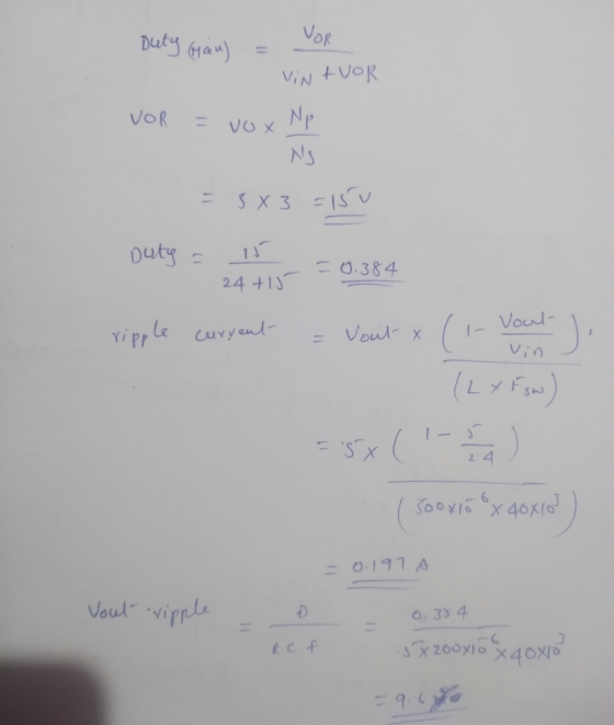
18 marks load with a power of 25.6 W.The cy f is 40kHz. sign a buck-boost converter to produce an output voltage of 16V a put voltage ripple must not exceed 1%. The dc input voltage is 24V. Th e swit...
 18 marks load with a power of 25.6 W.The cy f is 40kHz. sign a buck-boost converter to produce an output voltage of 16V a put voltage ripple must not exceed 1%. The dc input voltage is 24V. Th e switching frequen 121 a) the duty ratio b) Find the size of the inductor so that the maximum inductor current c) the size of the capacitor d) Assume L=1 00μH and the switching frequency fis variable. 141 121 Lma 10A...
Q4- A circuit diagram of a forward converter is shown in Fig. 3. V-200V, Vout-5V, fs= 100kHz, nún,-5, Lm-15m H, L=0.05...
 Q4- A circuit diagram of a forward converter is shown in Fig. 3. V-200V, Vout-5V, fs= 100kHz, nún,-5, Lm-15m H, L=0.05mH. (a) Find the maximum value of duty cycle. (b) If the duty cycle is 0.5, find the turns ratio ni:nz. (c) If n n is as calculated in (b), what is the lowest input voltage allowed if Vout is to be kept equal to 5V? D, n, n, A/ D3 O1 Fig. 3.
Q4- A circuit diagram of a...
Q4- A circuit diagram of a forward converter is shown in Fig. 3. V-200V, Vout-5V, fs= 100kHz, nún,-5, Lm-15m H, L=0.05mH. (a) Find the maximum value of duty cycle. (b) If the duty cycle is 0.5, find the turns ratio ni:nz. (c) If n n is as calculated in (b), what is the lowest input voltage allowed if Vout is to be kept equal to 5V? D, n, n, A/ D3 O1 Fig. 3.
Q4- A circuit diagram of a...
The boost converter of Figure below has the following parameters: Vs- 20V, duty cycle K- 0.6,...
 The boost converter of Figure below has the following parameters: Vs- 20V, duty cycle K- 0.6, R-12.5 Ohm, L-65 μΗ, C-200 μF and switching frequency f-40 kHz. Assume ideal components Determine: a) Output voltage b) Average, maximum, and minimum inductor current cOutput voltage ripple d) Average current in the diode Extra credit 2: provide simulation using any tool available to you. Compare results of simulation using ideal components and realistic ones and make meaningful conclusions (10%) ic V, Vo
1. (35 points) Switch mode DC DC Converters. a. (15 points) Design a flyback DC/DC power converter to the following specifications. Assume ideal components Input Voltage Output Voltage Output Powe...
 1. (35 points) Switch mode DC DC Converters. a. (15 points) Design a flyback DC/DC power converter to the following specifications. Assume ideal components Input Voltage Output Voltage Output Power Switching frequency Maximum Current Ripple in the filter inductor Output ripple voltage: Continuous conduction 170 VDC 12 VDC 40 Watts 750 kHz 1.2 Amps Your answer should include a circuit diagram with each energy storage element labeled with its value. Label the transformer turns ratio.
1. (35 points) Switch mode...
1. (35 points) Switch mode DC DC Converters. a. (15 points) Design a flyback DC/DC power converter to the following specifications. Assume ideal components Input Voltage Output Voltage Output Power Switching frequency Maximum Current Ripple in the filter inductor Output ripple voltage: Continuous conduction 170 VDC 12 VDC 40 Watts 750 kHz 1.2 Amps Your answer should include a circuit diagram with each energy storage element labeled with its value. Label the transformer turns ratio.
1. (35 points) Switch mode...
n,: n n D3 21 Fig. 3 Q4-A circuit diagram of a forward converter is shown in Fig. 3. У,-200V,Vur5V, f-100kHz, nj.n2-5,...
 n,: n n D3 21 Fig. 3 Q4-A circuit diagram of a forward converter is shown in Fig. 3. У,-200V,Vur5V, f-100kHz, nj.n2-5, Lm-15mH, L-0.05mH. (a) Find the maximum value of duty cycle. (b) If the duty cycle is 0.5, find the turns ratio n :n3. (c) If nn3 is as calculated in (b), what is the lowest input voltage allowed if Vout is to be kept equal to 5V?
n,: n n D3 21 Fig. 3 Q4-A circuit diagram of...
n,: n n D3 21 Fig. 3 Q4-A circuit diagram of a forward converter is shown in Fig. 3. У,-200V,Vur5V, f-100kHz, nj.n2-5, Lm-15mH, L-0.05mH. (a) Find the maximum value of duty cycle. (b) If the duty cycle is 0.5, find the turns ratio n :n3. (c) If nn3 is as calculated in (b), what is the lowest input voltage allowed if Vout is to be kept equal to 5V?
n,: n n D3 21 Fig. 3 Q4-A circuit diagram of...
Design a boost converter power stage to the following specification: Input voltage Output voltage: Output voltage...
 Design a boost converter power stage to the following specification: Input voltage Output voltage: Output voltage ripple:max 20mV Load power: Switching frequency: 15kHz 110-125V 300V 1.5kW Calculate: (i) Maximum duty cycle (ii) Minimum duty cycle (iii) Average diode current (iv) Assuming the Rds(on) of the MOSFET is 0.01 Ω, and the diode forward voltage is 0.8V, calculate the approximate efficiency of the circuit. 2. A switching power supply shown in the circuit below has its switch driven by a signal...
a9a resistive load. Inductor 3-(35 pts) Design a converter that has an input voltage of 24 V DC and supplies 18 V DC to current is desired to be continuous and must not change more than 30 % of i...
 a9a resistive load. Inductor 3-(35 pts) Design a converter that has an input voltage of 24 V DC and supplies 18 V DC to current is desired to be continuous and must not change more than 30 % of its average value voltage ripple must be lower than 2 %. Switching frequency is 10 kHz. a) Draw the circuit diagram. Calculate the duty ratio. Calculate values for 2 desired conditions of the inductor current and determine the value of the...
 Quiz 12
This flyback converter has the following parameters:
VS = 5.0 V D = 0.5 N2/N1 = 4
Switching Freq f = 150 kHz
C = 20 µF (micro F) Lm = 50 µH (micro H) R = 50 ?
(Ohms)
The capacitor is not ideal and has an RCesr = 0.4 ?
(Ohms).
The switch is not ideal and has Ron = 2 ? (Ohms).
Run a PSpice simulation with t = 6.0ms:
(a) Find the average output...
Quiz 12
This flyback converter has the following parameters:
VS = 5.0 V D = 0.5 N2/N1 = 4
Switching Freq f = 150 kHz
C = 20 µF (micro F) Lm = 50 µH (micro H) R = 50 ?
(Ohms)
The capacitor is not ideal and has an RCesr = 0.4 ?
(Ohms).
The switch is not ideal and has Ron = 2 ? (Ohms).
Run a PSpice simulation with t = 6.0ms:
(a) Find the average output...
 VI 100 L 100 100 1000uF 3 2. The flyback converter shown, operates at 10 kHz. The duty ratio of switch closed is D -0.2. The Primary to secondary ratio is 5 to 1 (N /N, -1/5, the load resistance is 15 . Determine: (a) Output voltage. (b) Average, minimum and maximum current in LI - Lm (the magnetizing inductance). (c) The output voltage ripple.
 D1 T1 c1 RL 15 3. The flyback converter shown, operates at 250 kHz. The 1 duty ratio ofswitch closed is D = 0.6. Determine: (a) Output voltage. (b) Average, minimum and maximum current in L1 (the magnetizing inductance.) (c) The output voltage ripple. Ll 1030uF 82
D1 T1 c1 RL 15 3. The flyback converter shown, operates at 250 kHz. The 1 duty ratio ofswitch closed is D = 0.6. Determine: (a) Output voltage. (b) Average, minimum and maximum...
D1 T1 c1 RL 15 3. The flyback converter shown, operates at 250 kHz. The 1 duty ratio ofswitch closed is D = 0.6. Determine: (a) Output voltage. (b) Average, minimum and maximum current in L1 (the magnetizing inductance.) (c) The output voltage ripple. Ll 1030uF 82
D1 T1 c1 RL 15 3. The flyback converter shown, operates at 250 kHz. The 1 duty ratio ofswitch closed is D = 0.6. Determine: (a) Output voltage. (b) Average, minimum and maximum...
 18 marks load with a power of 25.6 W.The cy f is 40kHz. sign a buck-boost converter to produce an output voltage of 16V a put voltage ripple must not exceed 1%. The dc input voltage is 24V. Th e switching frequen 121 a) the duty ratio b) Find the size of the inductor so that the maximum inductor current c) the size of the capacitor d) Assume L=1 00μH and the switching frequency fis variable. 141 121 Lma 10A...
 Q4- A circuit diagram of a forward converter is shown in Fig. 3. V-200V, Vout-5V, fs= 100kHz, nún,-5, Lm-15m H, L=0.05mH. (a) Find the maximum value of duty cycle. (b) If the duty cycle is 0.5, find the turns ratio ni:nz. (c) If n n is as calculated in (b), what is the lowest input voltage allowed if Vout is to be kept equal to 5V? D, n, n, A/ D3 O1 Fig. 3.
Q4- A circuit diagram of a...
Q4- A circuit diagram of a forward converter is shown in Fig. 3. V-200V, Vout-5V, fs= 100kHz, nún,-5, Lm-15m H, L=0.05mH. (a) Find the maximum value of duty cycle. (b) If the duty cycle is 0.5, find the turns ratio ni:nz. (c) If n n is as calculated in (b), what is the lowest input voltage allowed if Vout is to be kept equal to 5V? D, n, n, A/ D3 O1 Fig. 3.
Q4- A circuit diagram of a...
 The boost converter of Figure below has the following parameters: Vs- 20V, duty cycle K- 0.6, R-12.5 Ohm, L-65 μΗ, C-200 μF and switching frequency f-40 kHz. Assume ideal components Determine: a) Output voltage b) Average, maximum, and minimum inductor current cOutput voltage ripple d) Average current in the diode Extra credit 2: provide simulation using any tool available to you. Compare results of simulation using ideal components and realistic ones and make meaningful conclusions (10%) ic V, Vo
 1. (35 points) Switch mode DC DC Converters. a. (15 points) Design a flyback DC/DC power converter to the following specifications. Assume ideal components Input Voltage Output Voltage Output Power Switching frequency Maximum Current Ripple in the filter inductor Output ripple voltage: Continuous conduction 170 VDC 12 VDC 40 Watts 750 kHz 1.2 Amps Your answer should include a circuit diagram with each energy storage element labeled with its value. Label the transformer turns ratio.
1. (35 points) Switch mode...
1. (35 points) Switch mode DC DC Converters. a. (15 points) Design a flyback DC/DC power converter to the following specifications. Assume ideal components Input Voltage Output Voltage Output Power Switching frequency Maximum Current Ripple in the filter inductor Output ripple voltage: Continuous conduction 170 VDC 12 VDC 40 Watts 750 kHz 1.2 Amps Your answer should include a circuit diagram with each energy storage element labeled with its value. Label the transformer turns ratio.
1. (35 points) Switch mode...
 n,: n n D3 21 Fig. 3 Q4-A circuit diagram of a forward converter is shown in Fig. 3. У,-200V,Vur5V, f-100kHz, nj.n2-5, Lm-15mH, L-0.05mH. (a) Find the maximum value of duty cycle. (b) If the duty cycle is 0.5, find the turns ratio n :n3. (c) If nn3 is as calculated in (b), what is the lowest input voltage allowed if Vout is to be kept equal to 5V?
n,: n n D3 21 Fig. 3 Q4-A circuit diagram of...
n,: n n D3 21 Fig. 3 Q4-A circuit diagram of a forward converter is shown in Fig. 3. У,-200V,Vur5V, f-100kHz, nj.n2-5, Lm-15mH, L-0.05mH. (a) Find the maximum value of duty cycle. (b) If the duty cycle is 0.5, find the turns ratio n :n3. (c) If nn3 is as calculated in (b), what is the lowest input voltage allowed if Vout is to be kept equal to 5V?
n,: n n D3 21 Fig. 3 Q4-A circuit diagram of...
 Design a boost converter power stage to the following specification: Input voltage Output voltage: Output voltage ripple:max 20mV Load power: Switching frequency: 15kHz 110-125V 300V 1.5kW Calculate: (i) Maximum duty cycle (ii) Minimum duty cycle (iii) Average diode current (iv) Assuming the Rds(on) of the MOSFET is 0.01 Ω, and the diode forward voltage is 0.8V, calculate the approximate efficiency of the circuit. 2. A switching power supply shown in the circuit below has its switch driven by a signal...
 a9a resistive load. Inductor 3-(35 pts) Design a converter that has an input voltage of 24 V DC and supplies 18 V DC to current is desired to be continuous and must not change more than 30 % of its average value voltage ripple must be lower than 2 %. Switching frequency is 10 kHz. a) Draw the circuit diagram. Calculate the duty ratio. Calculate values for 2 desired conditions of the inductor current and determine the value of the...
Most questions answered within 3 hours.
-
MCL 445.111 et seq. deals with Home Solicitation Sales.
MCL stands for Michigan Compiled Laws which...
asked 5 minutes ago -
Which of the following items may not create an NOL?
a.
sole proprietorship loss
b.
personal...
asked 10 minutes ago -
A hypothetical solution forms between a solid and a liquid. The
values of the thermodynamic quantities...
asked 8 minutes ago -
when 2053 j of heat is added to 46.3 g of hexane C6H14 the
temperature increases...
asked 11 minutes ago -
a)An ideal heat pump is being considered for use in heating an
environment with a temperature...
asked 11 minutes ago -
.
Convert the following pairs of voltage and current waveforms to
phasor form. Each pair of...
asked 13 minutes ago -
I need new and unique answers, please. (Use your own words,
don't copy and paste), Please...
asked 14 minutes ago -
A 6.5 cm diameter ball has a terminal speed of 22 m/s. What is
the ball's...
asked 27 minutes ago -
Name two areas of the human body with the highest concentration
of lymph nodes and speculate...
asked 30 minutes ago -
Angel Corporation has $10,000,000 of
8.0% 25 year bonds dated May 1, 2018 with interest payable...
asked 1 hour ago -
7.
________ involves individuals trading goods they already have or
providing services in exchange for something...
asked 1 hour ago -
Share your research problem. What databases did you search as
you gathered evidence to support your...
asked 1 hour ago