
Homework Answers

![МА ak T 1 07 ISU © Ge diode conducting, then chenck Anode to - from Here we can say Dr is off -15+2K] +0.7 +2101-0 aton un I](http://img.homeworklib.com/questions/93d3e9a0-5b90-11eb-a4ff-971d9837d639.png?x-oss-process=image/resize,w_560)
Add Answer to:
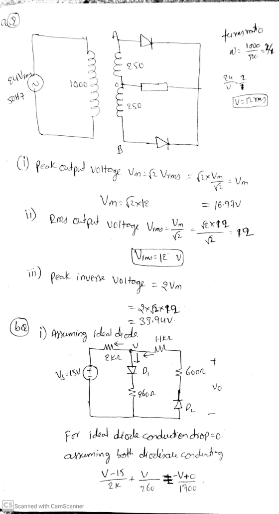
Fral Assignment (a) Draw the circuit diagram a Centre tapped Pull Wave Rectifier using a 1000-500...
3. Consider the full-wave bridge rectifier circuit shown below. The full-wave bridge is made using silicon...
 3. Consider the full-wave bridge rectifier circuit shown below. The full-wave bridge is made using silicon diodes. 120V 15V 120 V(ms) n 60 Hz 752 Vout a. Find the maximum value of VoUT, and the voltage rating for the capacitor assuming a 50% margin of safety. b. Choose the capacitance of the filter capacitor for a peak-to-peak ripple of 1V, and determine the corresponding peak diode current. What is the frequency of the ripple voltage? c. Now suppose the filter...
5. (10 points) The op amp in the precision rectifier circuit shown is ideal with output...
 5. (10 points) The op amp in the precision rectifier circuit shown is ideal with output saturation levels of = 14 V. Assume that when conducting the diode exhibits a constant voltage drop of 0.7 V, R1 = R2 = R3 =1 k2, and R4 = R5 = 2 k22. Find Vout (in V) when Vs = -2 V? Vout(Vs = -2) = -15V VEE LM348N LM348N 15V VCC
Design a FULL WAVE BRIDGE RECTIFIER circuit that will: Take 120volts ac, 60 hz, sinusoidal waveform...
 Design a FULL WAVE BRIDGE RECTIFIER circuit that will:
Take 120volts ac, 60 hz, sinusoidal waveform and convert
it to a “regulated “dc value
giving 12 volts +, - 1 volt across a 2000-ohm output
load resistor with no more than 2%
ripple voltage.
You may assume:
a. An ideal power transformer as discussed in class.
b. For hand computations, you must assume a diode given by
Figure 4.8 page 185.
c. A filter capacitor sized per the textbook equation...
Design a FULL WAVE BRIDGE RECTIFIER circuit that will:
Take 120volts ac, 60 hz, sinusoidal waveform and convert
it to a “regulated “dc value
giving 12 volts +, - 1 volt across a 2000-ohm output
load resistor with no more than 2%
ripple voltage.
You may assume:
a. An ideal power transformer as discussed in class.
b. For hand computations, you must assume a diode given by
Figure 4.8 page 185.
c. A filter capacitor sized per the textbook equation...
2. Consider the full-wave rectifier circuit in below. The output resistance is R - 125 12,...
 2. Consider the full-wave rectifier circuit in below. The output resistance is R - 125 12, each diode cut-in voltage is V, -0.7 V, and the frequency of the input signal is 60 Hz. If a filter capacitor will be connected in parallel with R. The magnitude of the peak output voltage is to be 15 V and the ripple voltage is to be no more than 0.35 V. (a) Determine the rms value of vs and (b) the required...
4.70 A full-wave bridge-rectifier circuit with a 500-22 load operates from a 120-V (rms) 60-Hz household...
 4.70 A full-wave bridge-rectifier circuit with a 500-22 load operates from a 120-V (rms) 60-Hz household supply through a 6-to-1 step-down transformer having a single Secondary winding. It uses four diodes, each of which can be modeled to have a 0.7-V drop for any current. What is the peak value of the rectified voltage across the load? For what fraction of a cycle does each diode conduct? What is the average voltage across the load? What is the average current...
1. The following half-wave rectifier circuit has a 120-Vrms source at 60-Hz, R-500-2, and C-100-uF. Determine:...
 1. The following half-wave rectifier circuit has a 120-Vrms source at 60-Hz, R-500-2, and C-100-uF. Determine: a) An expression for the output voltage. b) The peak-to-peak voltage variation on the output. c) An expression for capacitor current. d) The peak diode current. e) Confirm your answers through OrCAD solution. Display all graphs and tabulate the results ID IR le Vs Vm Sin(wt) R. T100 Vo soon
 3. Consider the full-wave bridge rectifier circuit shown below. The full-wave bridge is made using silicon diodes. 120V 15V 120 V(ms) n 60 Hz 752 Vout a. Find the maximum value of VoUT, and the voltage rating for the capacitor assuming a 50% margin of safety. b. Choose the capacitance of the filter capacitor for a peak-to-peak ripple of 1V, and determine the corresponding peak diode current. What is the frequency of the ripple voltage? c. Now suppose the filter...
 5. (10 points) The op amp in the precision rectifier circuit shown is ideal with output saturation levels of = 14 V. Assume that when conducting the diode exhibits a constant voltage drop of 0.7 V, R1 = R2 = R3 =1 k2, and R4 = R5 = 2 k22. Find Vout (in V) when Vs = -2 V? Vout(Vs = -2) = -15V VEE LM348N LM348N 15V VCC
 Design a FULL WAVE BRIDGE RECTIFIER circuit that will:
Take 120volts ac, 60 hz, sinusoidal waveform and convert
it to a “regulated “dc value
giving 12 volts +, - 1 volt across a 2000-ohm output
load resistor with no more than 2%
ripple voltage.
You may assume:
a. An ideal power transformer as discussed in class.
b. For hand computations, you must assume a diode given by
Figure 4.8 page 185.
c. A filter capacitor sized per the textbook equation...
Design a FULL WAVE BRIDGE RECTIFIER circuit that will:
Take 120volts ac, 60 hz, sinusoidal waveform and convert
it to a “regulated “dc value
giving 12 volts +, - 1 volt across a 2000-ohm output
load resistor with no more than 2%
ripple voltage.
You may assume:
a. An ideal power transformer as discussed in class.
b. For hand computations, you must assume a diode given by
Figure 4.8 page 185.
c. A filter capacitor sized per the textbook equation...
 2. Consider the full-wave rectifier circuit in below. The output resistance is R - 125 12, each diode cut-in voltage is V, -0.7 V, and the frequency of the input signal is 60 Hz. If a filter capacitor will be connected in parallel with R. The magnitude of the peak output voltage is to be 15 V and the ripple voltage is to be no more than 0.35 V. (a) Determine the rms value of vs and (b) the required...
 4.70 A full-wave bridge-rectifier circuit with a 500-22 load operates from a 120-V (rms) 60-Hz household supply through a 6-to-1 step-down transformer having a single Secondary winding. It uses four diodes, each of which can be modeled to have a 0.7-V drop for any current. What is the peak value of the rectified voltage across the load? For what fraction of a cycle does each diode conduct? What is the average voltage across the load? What is the average current...
 1. The following half-wave rectifier circuit has a 120-Vrms source at 60-Hz, R-500-2, and C-100-uF. Determine: a) An expression for the output voltage. b) The peak-to-peak voltage variation on the output. c) An expression for capacitor current. d) The peak diode current. e) Confirm your answers through OrCAD solution. Display all graphs and tabulate the results ID IR le Vs Vm Sin(wt) R. T100 Vo soon
Most questions answered within 3 hours.
-
Two narrow, parallel slits separated by 0.850 mm are illuminated
by 570-nm light, and the viewing...
asked 5 minutes ago -
Write a balanced equation for the double-replacement
precipitation reaction described, using the smallest possible
integer coefficients....
asked 4 minutes ago -
Would You expect the analysis produced by the Legislative
Analyst’s Office to be more or less...
asked 21 minutes ago -
How configuring websites to use a common NFS share could
strengthen business continuity efforts
asked 22 minutes ago -
Arrange the following aqueous solutions in order of increasing
boiling point: 0.25 m NaCl (sodium chloride)...
asked 22 minutes ago -
calculate the mass of forsterite (Mg2SiO4) that contains a
million (1.00•10^6) oxygen
asked 46 minutes ago -
A heat engine has an efficiency of 0.48. Initially,
the engine performs net work W per...
asked 36 minutes ago -
identify the effect on the financial statement on the
following senarios:
b) the clients business mainly...
asked 33 minutes ago -
Whenever two Apollo astronauts were on the surface of the Moon,
a third astronaut orbited the...
asked 43 minutes ago -
Suppose that Marriott’s production process is characterized by
constant returns to scale at all output levels....
asked 43 minutes ago -
If a customer places a buy order for one millisecond only on an
electronic limit order...
asked 51 minutes ago -
An aqueous solution of perchloric acid is
standardized by titration with a 0.101 M solution
of...
asked 1 hour ago