
Homework Answers
Add Answer to:
3. Consider the full-wave bridge rectifier circuit shown below. The full-wave bridge is made using silicon...
1. Power supply (ac to dc) design. [10 pts.] Design a full-wave bridge rectifier circuit to deliv...
 1. Power supply (ac to dc) design. [10 pts.] Design a full-wave bridge rectifier circuit to deliver 10 volts dc with less than 0.1 volt (peak to peak) ripple into a load drawing up to 10 mA. (a) Choose the appropriate ac input voltage from the transformer secondary assuming the usual voltage drops for silicon diodes. (b) Determine the correct capacitor value to ensure the specified ripple in your calculation (c) What fuse value should you select for the primary...
Consider the single-phase full-wave rectifier circuit shown below with a sinusoidal input vs 120 Vrms at...
 Consider the single-phase full-wave rectifier circuit shown below with a sinusoidal input vs 120 Vrms at 60 Hz and a load R= 250 TiD DAZ 40 AD AD ww D (a) (b) Consider adding a filter capacitor to the full-wave rectifier in Problem 3 to reduce the output ripple (a) Calculate the minimum value of capacitance required to reduce the output voltage ripple to 1 % of the average value (b) Calculate the average output current (c) Calculate the average...
Design a FULL WAVE BRIDGE RECTIFIER circuit that will: Take 120volts ac, 60 hz, sinusoidal waveform...
 Design a FULL WAVE BRIDGE RECTIFIER circuit that will:
Take 120volts ac, 60 hz, sinusoidal waveform and convert
it to a “regulated “dc value
giving 12 volts +, - 1 volt across a 2000-ohm output
load resistor with no more than 2%
ripple voltage.
You may assume:
a. An ideal power transformer as discussed in class.
b. For hand computations, you must assume a diode given by
Figure 4.8 page 185.
c. A filter capacitor sized per the textbook equation...
Design a FULL WAVE BRIDGE RECTIFIER circuit that will:
Take 120volts ac, 60 hz, sinusoidal waveform and convert
it to a “regulated “dc value
giving 12 volts +, - 1 volt across a 2000-ohm output
load resistor with no more than 2%
ripple voltage.
You may assume:
a. An ideal power transformer as discussed in class.
b. For hand computations, you must assume a diode given by
Figure 4.8 page 185.
c. A filter capacitor sized per the textbook equation...
3. For the regulated power supply shown in Figure 5-3, which is a full-wave bridge rectifier...
 3. For the regulated power supply shown in Figure 5-3, which is a full-wave bridge rectifier containing ter combined with a Zener diode voltage regulator, determine the load voltage VI, load current Ir, source current Is, Zener current Iz and the ripple voltage at the input and output of the regulator, and r(p-p)y respectively, and the ripple frequency fr a fil- VL Ir. Is Iz=. (d-4)1a Ur(p-P) Is V' 1N4002GP Vout = VL + Iz IL 100 V2 120 V...
D *4.80 It is required to use a peak rectifier to design a de power supply...
 D *4.80 It is required to use a peak rectifier to design a de power supply that provides an average de output voltage of 12 V on which a maximum of ±1-V ripple is allowed. The rectifier feeds a load of 200 2. The rectifier is fed from the line voltage (120 V rms, 60 Hz) through a transformer. The diodes available have 0.7-V drop when conducting. If the designer opts for the half-wave circuit: (a) Specify the rms voltage...
2. Consider the full-wave rectifier circuit in below. The output resistance is R - 125 12,...
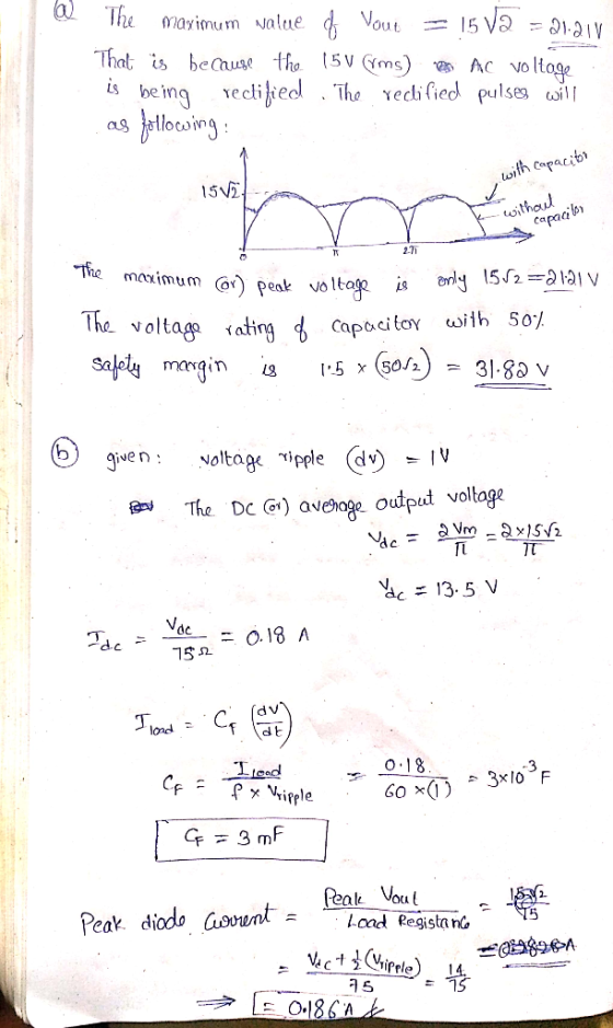
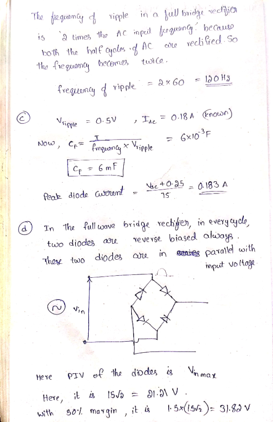
 2. Consider the full-wave rectifier circuit in below. The output resistance is R - 125 12, each diode cut-in voltage is V, -0.7 V, and the frequency of the input signal is 60 Hz. If a filter capacitor will be connected in parallel with R. The magnitude of the peak output voltage is to be 15 V and the ripple voltage is to be no more than 0.35 V. (a) Determine the rms value of vs and (b) the required...
In the circuit shown, a center-tapped transformer is used to create a full- wave center-tapped configuration....
 In the circuit shown, a center-tapped transformer is used to create a full- wave center-tapped configuration. Note that half of the secondary voltage appears across each half winding. 120V : 7.8V 120 Vrms) 60 Hz of 7 R } Vout a. Find the maximum value of Vout. Note that half of the total secondary voltage appears across each half of the secondary. b. Suppose the load resistance is 10 ohms. Find the required filter capacitance so that the peak-to-peak ripple...
3. Perform the following calculations for the full-wave rectifier with filter capacitor in Fig. 5 Determine...
 3. Perform the following calculations for the full-wave rectifier with filter capacitor in Fig. 5 Determine the maximum value of vo(f), vOpeak a. b. Determine the peak-to-peak ripple voltage, vr, peak-peak Determine the approximate average value of vo(t). You do not have to use integration. Assume the ripple waveform has an ideal sawtooth shape with each "tooth" being a right triangle having amplitude vr peak-peak as in Fig. 6 C. d. Sketch a realistic ripple waveform superimposed on the unfiltered...
Consider the full-wave rectifier circuit below. Use a constant voltage drop model for the diodes with...
 Consider the full-wave rectifier circuit below. Use a constant voltage drop model for the diodes with VD 1. 0.7 V. Let v": 10 sin(2n(2000 and RI-100Q. (6 pt) Calelae the average vales of oun uinege D1 D4 V1 R1 with respect to time or angle. out b. (2+3 pts) A capacitor is placed across RI to reduce the ripple to D3 D2 20 mVp-p. Find the capacitor value. (2+3 pts) Calculate the approximate average Vout value assuming a 20 m...
Fral Assignment (a) Draw the circuit diagram a Centre tapped Pull Wave Rectifier using a 1000-500...
 Fral Assignment (a) Draw the circuit diagram a Centre tapped Pull Wave Rectifier using a 1000-500 Centre tapped Transformer. Assume a signal of 24 V, 50 Hz at the primary of the transformer Assume silicon diodes. Find: (11) Peak Output Voltage, Volt RMS Output Voltage, Vor). the peak inverse voltage [3 Mark) (b) Find the current flowing through the R1,R2,R3 and R4 and Vx. If Vs=15v,RI-2K22,R2-26092, R3=1.122 and R4-60002. (1) Assuming Ideal diode (2) Si diode (3) Ge diode [3...
 1. Power supply (ac to dc) design. [10 pts.] Design a full-wave bridge rectifier circuit to deliver 10 volts dc with less than 0.1 volt (peak to peak) ripple into a load drawing up to 10 mA. (a) Choose the appropriate ac input voltage from the transformer secondary assuming the usual voltage drops for silicon diodes. (b) Determine the correct capacitor value to ensure the specified ripple in your calculation (c) What fuse value should you select for the primary...
 Consider the single-phase full-wave rectifier circuit shown below with a sinusoidal input vs 120 Vrms at 60 Hz and a load R= 250 TiD DAZ 40 AD AD ww D (a) (b) Consider adding a filter capacitor to the full-wave rectifier in Problem 3 to reduce the output ripple (a) Calculate the minimum value of capacitance required to reduce the output voltage ripple to 1 % of the average value (b) Calculate the average output current (c) Calculate the average...
 Design a FULL WAVE BRIDGE RECTIFIER circuit that will:
Take 120volts ac, 60 hz, sinusoidal waveform and convert
it to a “regulated “dc value
giving 12 volts +, - 1 volt across a 2000-ohm output
load resistor with no more than 2%
ripple voltage.
You may assume:
a. An ideal power transformer as discussed in class.
b. For hand computations, you must assume a diode given by
Figure 4.8 page 185.
c. A filter capacitor sized per the textbook equation...
Design a FULL WAVE BRIDGE RECTIFIER circuit that will:
Take 120volts ac, 60 hz, sinusoidal waveform and convert
it to a “regulated “dc value
giving 12 volts +, - 1 volt across a 2000-ohm output
load resistor with no more than 2%
ripple voltage.
You may assume:
a. An ideal power transformer as discussed in class.
b. For hand computations, you must assume a diode given by
Figure 4.8 page 185.
c. A filter capacitor sized per the textbook equation...
 3. For the regulated power supply shown in Figure 5-3, which is a full-wave bridge rectifier containing ter combined with a Zener diode voltage regulator, determine the load voltage VI, load current Ir, source current Is, Zener current Iz and the ripple voltage at the input and output of the regulator, and r(p-p)y respectively, and the ripple frequency fr a fil- VL Ir. Is Iz=. (d-4)1a Ur(p-P) Is V' 1N4002GP Vout = VL + Iz IL 100 V2 120 V...
 D *4.80 It is required to use a peak rectifier to design a de power supply that provides an average de output voltage of 12 V on which a maximum of ±1-V ripple is allowed. The rectifier feeds a load of 200 2. The rectifier is fed from the line voltage (120 V rms, 60 Hz) through a transformer. The diodes available have 0.7-V drop when conducting. If the designer opts for the half-wave circuit: (a) Specify the rms voltage...
 2. Consider the full-wave rectifier circuit in below. The output resistance is R - 125 12, each diode cut-in voltage is V, -0.7 V, and the frequency of the input signal is 60 Hz. If a filter capacitor will be connected in parallel with R. The magnitude of the peak output voltage is to be 15 V and the ripple voltage is to be no more than 0.35 V. (a) Determine the rms value of vs and (b) the required...
 In the circuit shown, a center-tapped transformer is used to create a full- wave center-tapped configuration. Note that half of the secondary voltage appears across each half winding. 120V : 7.8V 120 Vrms) 60 Hz of 7 R } Vout a. Find the maximum value of Vout. Note that half of the total secondary voltage appears across each half of the secondary. b. Suppose the load resistance is 10 ohms. Find the required filter capacitance so that the peak-to-peak ripple...
 3. Perform the following calculations for the full-wave rectifier with filter capacitor in Fig. 5 Determine the maximum value of vo(f), vOpeak a. b. Determine the peak-to-peak ripple voltage, vr, peak-peak Determine the approximate average value of vo(t). You do not have to use integration. Assume the ripple waveform has an ideal sawtooth shape with each "tooth" being a right triangle having amplitude vr peak-peak as in Fig. 6 C. d. Sketch a realistic ripple waveform superimposed on the unfiltered...
 Consider the full-wave rectifier circuit below. Use a constant voltage drop model for the diodes with VD 1. 0.7 V. Let v": 10 sin(2n(2000 and RI-100Q. (6 pt) Calelae the average vales of oun uinege D1 D4 V1 R1 with respect to time or angle. out b. (2+3 pts) A capacitor is placed across RI to reduce the ripple to D3 D2 20 mVp-p. Find the capacitor value. (2+3 pts) Calculate the approximate average Vout value assuming a 20 m...
 Fral Assignment (a) Draw the circuit diagram a Centre tapped Pull Wave Rectifier using a 1000-500 Centre tapped Transformer. Assume a signal of 24 V, 50 Hz at the primary of the transformer Assume silicon diodes. Find: (11) Peak Output Voltage, Volt RMS Output Voltage, Vor). the peak inverse voltage [3 Mark) (b) Find the current flowing through the R1,R2,R3 and R4 and Vx. If Vs=15v,RI-2K22,R2-26092, R3=1.122 and R4-60002. (1) Assuming Ideal diode (2) Si diode (3) Ge diode [3...
Most questions answered within 3 hours.
-
For the following reaction:
IBr(g) + 4F2(g) → IF5(g) +
BrF3(g)
Compound
ΔH°f (kJ mol-1)...
asked 1 minute ago -
Assuming the simple probability of even A is given as P(A) and
the simple probability of...
asked 3 minutes ago -
2.- It is known that 20% of the students on campus are smokers.
If 8 students...
asked 4 minutes ago -
Provide a summary/reflection of what you gleaned of how law
enforcement is effect by Unconventional Weapons...
asked 24 minutes ago -
From the following heats of combustion,
CH3OH(l) + 3/2O2(g) → CO2(g) +
2H2O(l)
ΔHorxn = –726.4...
asked 18 minutes ago -
Floating Point Representation
Consider a computer that stores information using 10 bits words.
The first bit...
asked 47 minutes ago -
. The theoretical weight percent of carbon in (CH3)3N is:
A. 20.32% B. 81.95% C. 9.97%...
asked 40 minutes ago -
The rate of a certain reaction is given by the following rate
law:
rate = k[H2][I2]...
asked 35 minutes ago -
A 10,000 uF capacitor is in series with a 1 uH inductor. What is
Zeq of...
asked 39 minutes ago -
Draw the molecular orbital diagram for O2-
(oxygen molecule with a negative charge).
asked 56 minutes ago -
Of all the different weapons discussed in this chapter that make
up CBRNE,
Which group do...
asked 53 minutes ago -
Given the following JavaScript code, what will be displayed on
the web page?
var x =...
asked 1 hour ago