
Homework Answers

Add Answer to:
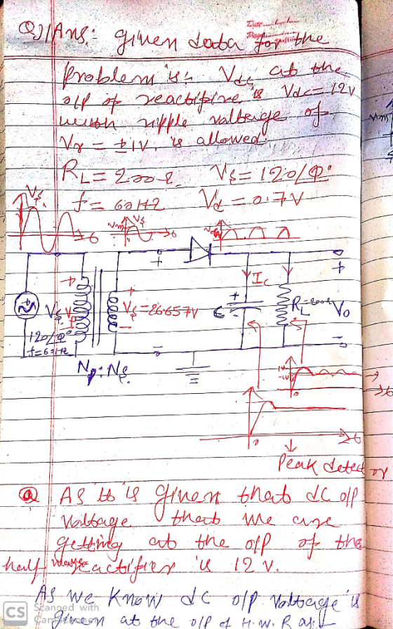
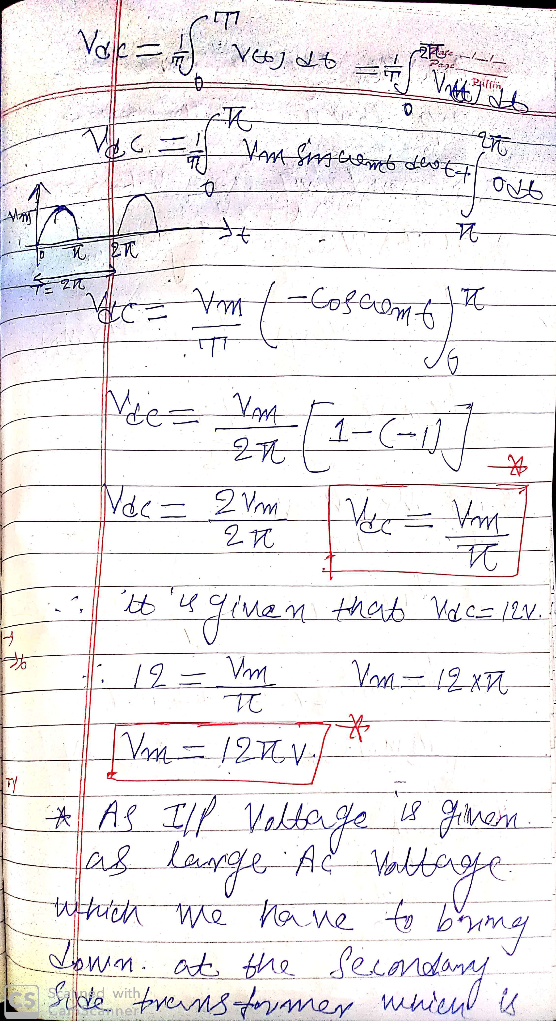
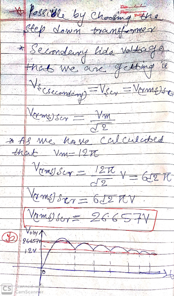
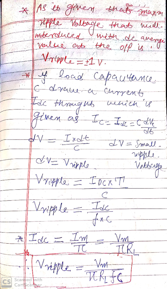
D *4.80 It is required to use a peak rectifier to design a de power supply...
Design a FULL WAVE BRIDGE RECTIFIER circuit that will: Take 120volts ac, 60 hz, sinusoidal waveform...
 Design a FULL WAVE BRIDGE RECTIFIER circuit that will:
Take 120volts ac, 60 hz, sinusoidal waveform and convert
it to a “regulated “dc value
giving 12 volts +, - 1 volt across a 2000-ohm output
load resistor with no more than 2%
ripple voltage.
You may assume:
a. An ideal power transformer as discussed in class.
b. For hand computations, you must assume a diode given by
Figure 4.8 page 185.
c. A filter capacitor sized per the textbook equation...
Design a FULL WAVE BRIDGE RECTIFIER circuit that will:
Take 120volts ac, 60 hz, sinusoidal waveform and convert
it to a “regulated “dc value
giving 12 volts +, - 1 volt across a 2000-ohm output
load resistor with no more than 2%
ripple voltage.
You may assume:
a. An ideal power transformer as discussed in class.
b. For hand computations, you must assume a diode given by
Figure 4.8 page 185.
c. A filter capacitor sized per the textbook equation...
It is required to use a FULL-wave rectifier to design a dc power supply that provides...
It is required to use a FULL-wave rectifier to design a dc power supply that provides an average dc output voltage of 15 V. A maximum ripple voltage of ±1 V is allowed on the output voltage. The output voltage will feed a load resistance of 250 Ω. Assume a sinusoidal input voltage with the frequency of 60 Hz. Do not include a Zener diode in your design. (Assume V_D0)* = 0.7 V). a) Draw the circuit diagram. b) Calculate...
3. Consider the full-wave bridge rectifier circuit shown below. The full-wave bridge is made using silicon...
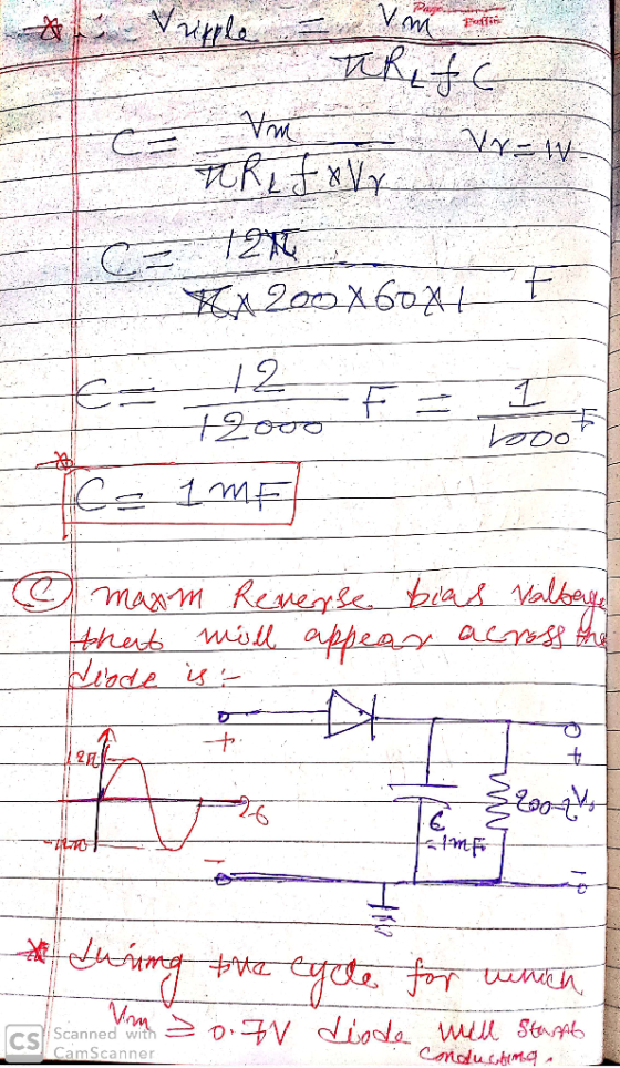
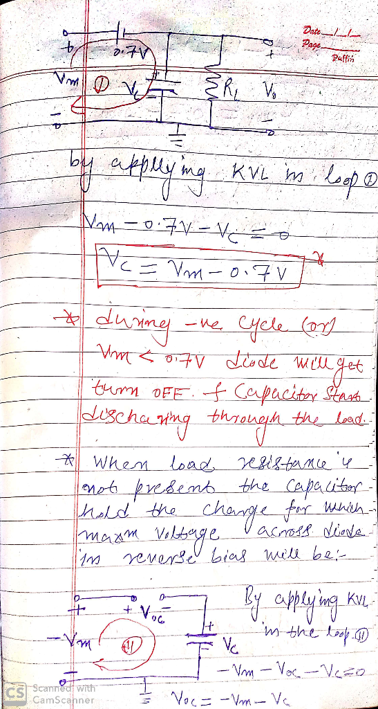
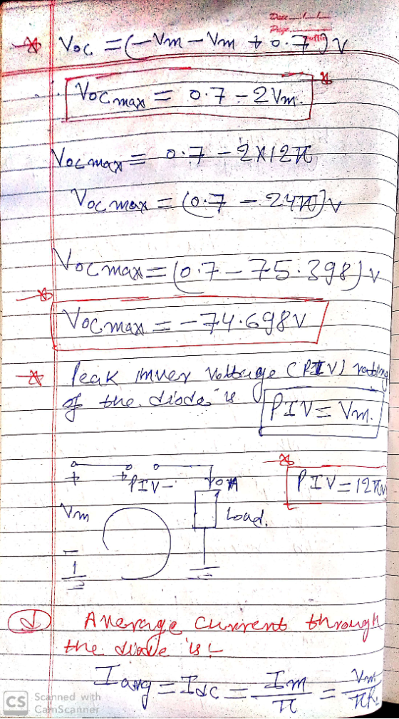
 3. Consider the full-wave bridge rectifier circuit shown below. The full-wave bridge is made using silicon diodes. 120V 15V 120 V(ms) n 60 Hz 752 Vout a. Find the maximum value of VoUT, and the voltage rating for the capacitor assuming a 50% margin of safety. b. Choose the capacitance of the filter capacitor for a peak-to-peak ripple of 1V, and determine the corresponding peak diode current. What is the frequency of the ripple voltage? c. Now suppose the filter...
You need to design a DC power supply that provides an average DC output voltage of...
 You need to design a DC power supply that provides an average DC output voltage of 5V to charge your cellphone. The maximum allowed ripple at the output is ±200 mV. Your cellphone can be modeled as a 1 50Ω load. You have to use a bridge rectifier with four diodes. Note: For calculations, consider constant voltage drop model of the diode with V0 = 0.7V. (a) The charger is designed to use in the US, i.e. transformer primary is...
Use a transformer, a bridge rectifier IC, and a capacitor to design a battery charger. If...
Use a transformer, a bridge rectifier IC, and a capacitor to design a battery charger. If the input power is from the regular power line (120rms, 60Hz) and the battery is 12-V battery. The peak-to-peak ripple voltage across the battery should be no more than 2V. Assume the battery internal resistance is 100. 1) Draw the circuit diagram; 2) Explain how it works; 3) Specify the value of the turns ratio of the transformer and peak inverse voltage of diode....
Even just steps/formula on what to follow would be sufficient if you cannot complete the question.
 Even just steps/formula on what to follow would be sufficient if
you cannot complete the question.
Draw a bridge rectifier fed from a single-phase 240-V (Au) supply with a 4:1 step down transformer. A 10-2 load is connected to the output. Assume a simplified model for the diodes with VoN 1V per diode and zero leakage current. (a) Draw voltage, current and p(t) waveforms for one diode. (b) Derive the diode voltage spec from the voltage waveforms, and add 50%...
Even just steps/formula on what to follow would be sufficient if
you cannot complete the question.
Draw a bridge rectifier fed from a single-phase 240-V (Au) supply with a 4:1 step down transformer. A 10-2 load is connected to the output. Assume a simplified model for the diodes with VoN 1V per diode and zero leakage current. (a) Draw voltage, current and p(t) waveforms for one diode. (b) Derive the diode voltage spec from the voltage waveforms, and add 50%...
4.70 A full-wave bridge-rectifier circuit with a 500-22 load operates from a 120-V (rms) 60-Hz household...
 4.70 A full-wave bridge-rectifier circuit with a 500-22 load operates from a 120-V (rms) 60-Hz household supply through a 6-to-1 step-down transformer having a single Secondary winding. It uses four diodes, each of which can be modeled to have a 0.7-V drop for any current. What is the peak value of the rectified voltage across the load? For what fraction of a cycle does each diode conduct? What is the average voltage across the load? What is the average current...
VOLTAGE-DIVIDER BIAS 179 CONFIGURATION h determined in Example 4.7. Essentially, exact and approx...
 VOLTAGE-DIVIDER BIAS 179 CONFIGURATION h determined in Example 4.7. Essentially, exact and approximate techniques is the ten the 07 step down transformer and a load RL of 820 ohms. It is connected to an ac source of 100 VAC rms, 50 Hz. (hint: note the rms values, and for diode PIV, assume ideal diodes and draw the PIV eqv ckts) ve rectifier circuit has a 10:1 3. A positive output, a. Draw this circuit.. b. Find Vp and Vave at...
Exercise#2 • An AC supply of 230V rms is applied to a half wave rectifier circuit...
 Exercise#2 • An AC supply of 230V rms is applied to a half wave rectifier circuit through a transformer of turn ratio 5:1. Assume the diode is an ideal one. The load resistance is 30092. * Find (a) peak load current (b) the dc load current (c) the rms load current (d) TUF (e) PIV (f) FF (g) RF (h) power delivered to load
1. Power supply (ac to dc) design. [10 pts.] Design a full-wave bridge rectifier circuit to deliv...
 1. Power supply (ac to dc) design. [10 pts.] Design a full-wave bridge rectifier circuit to deliver 10 volts dc with less than 0.1 volt (peak to peak) ripple into a load drawing up to 10 mA. (a) Choose the appropriate ac input voltage from the transformer secondary assuming the usual voltage drops for silicon diodes. (b) Determine the correct capacitor value to ensure the specified ripple in your calculation (c) What fuse value should you select for the primary...
 Design a FULL WAVE BRIDGE RECTIFIER circuit that will:
Take 120volts ac, 60 hz, sinusoidal waveform and convert
it to a “regulated “dc value
giving 12 volts +, - 1 volt across a 2000-ohm output
load resistor with no more than 2%
ripple voltage.
You may assume:
a. An ideal power transformer as discussed in class.
b. For hand computations, you must assume a diode given by
Figure 4.8 page 185.
c. A filter capacitor sized per the textbook equation...
Design a FULL WAVE BRIDGE RECTIFIER circuit that will:
Take 120volts ac, 60 hz, sinusoidal waveform and convert
it to a “regulated “dc value
giving 12 volts +, - 1 volt across a 2000-ohm output
load resistor with no more than 2%
ripple voltage.
You may assume:
a. An ideal power transformer as discussed in class.
b. For hand computations, you must assume a diode given by
Figure 4.8 page 185.
c. A filter capacitor sized per the textbook equation...
 3. Consider the full-wave bridge rectifier circuit shown below. The full-wave bridge is made using silicon diodes. 120V 15V 120 V(ms) n 60 Hz 752 Vout a. Find the maximum value of VoUT, and the voltage rating for the capacitor assuming a 50% margin of safety. b. Choose the capacitance of the filter capacitor for a peak-to-peak ripple of 1V, and determine the corresponding peak diode current. What is the frequency of the ripple voltage? c. Now suppose the filter...
 You need to design a DC power supply that provides an average DC output voltage of 5V to charge your cellphone. The maximum allowed ripple at the output is ±200 mV. Your cellphone can be modeled as a 1 50Ω load. You have to use a bridge rectifier with four diodes. Note: For calculations, consider constant voltage drop model of the diode with V0 = 0.7V. (a) The charger is designed to use in the US, i.e. transformer primary is...
 Even just steps/formula on what to follow would be sufficient if
you cannot complete the question.
Draw a bridge rectifier fed from a single-phase 240-V (Au) supply with a 4:1 step down transformer. A 10-2 load is connected to the output. Assume a simplified model for the diodes with VoN 1V per diode and zero leakage current. (a) Draw voltage, current and p(t) waveforms for one diode. (b) Derive the diode voltage spec from the voltage waveforms, and add 50%...
Even just steps/formula on what to follow would be sufficient if
you cannot complete the question.
Draw a bridge rectifier fed from a single-phase 240-V (Au) supply with a 4:1 step down transformer. A 10-2 load is connected to the output. Assume a simplified model for the diodes with VoN 1V per diode and zero leakage current. (a) Draw voltage, current and p(t) waveforms for one diode. (b) Derive the diode voltage spec from the voltage waveforms, and add 50%...
 4.70 A full-wave bridge-rectifier circuit with a 500-22 load operates from a 120-V (rms) 60-Hz household supply through a 6-to-1 step-down transformer having a single Secondary winding. It uses four diodes, each of which can be modeled to have a 0.7-V drop for any current. What is the peak value of the rectified voltage across the load? For what fraction of a cycle does each diode conduct? What is the average voltage across the load? What is the average current...
 VOLTAGE-DIVIDER BIAS 179 CONFIGURATION h determined in Example 4.7. Essentially, exact and approximate techniques is the ten the 07 step down transformer and a load RL of 820 ohms. It is connected to an ac source of 100 VAC rms, 50 Hz. (hint: note the rms values, and for diode PIV, assume ideal diodes and draw the PIV eqv ckts) ve rectifier circuit has a 10:1 3. A positive output, a. Draw this circuit.. b. Find Vp and Vave at...
 Exercise#2 • An AC supply of 230V rms is applied to a half wave rectifier circuit through a transformer of turn ratio 5:1. Assume the diode is an ideal one. The load resistance is 30092. * Find (a) peak load current (b) the dc load current (c) the rms load current (d) TUF (e) PIV (f) FF (g) RF (h) power delivered to load
 1. Power supply (ac to dc) design. [10 pts.] Design a full-wave bridge rectifier circuit to deliver 10 volts dc with less than 0.1 volt (peak to peak) ripple into a load drawing up to 10 mA. (a) Choose the appropriate ac input voltage from the transformer secondary assuming the usual voltage drops for silicon diodes. (b) Determine the correct capacitor value to ensure the specified ripple in your calculation (c) What fuse value should you select for the primary...
Most questions answered within 3 hours.
-
A 8.15- g bullet from a 9-mm pistol has a velocity of 366.0 m/s.
It strikes...
asked 34 minutes ago -
The outstanding bonds of Alpha Extracts have a yield to maturity
of 7.4 percent and a...
asked 30 minutes ago -
The Problem: The Case of the Harmonizing Vacations
Your CEO is exploring partnering with a European...
asked 1 hour ago -
A chemical equation is balanced by adding coefficients in front
of some formulas so that the...
asked 1 hour ago -
From the literature (reference your sources): What are the
lattice parameters of calcite and aragonite? Why...
asked 2 hours ago -
Your system is rejecting the question am asking which is
preceded by a case study. It...
asked 2 hours ago -
3. On January 2, 2000, Larry creates a trust with himself as
trustee. Larry as trustee...
asked 2 hours ago -
A member of the volleyball team spikes the ball. During this
process, she changes the velocity...
asked 2 hours ago -
Are adult gamers less likely to use a gaming console (Xbox,
PlayStation, Wii, etc...) than teen...
asked 3 hours ago -
The University of
Texas recently reported that 43% of college students aged 18-24
would spend their...
asked 3 hours ago -
The length of stay at a specific emergency department in
Phoenix, Arizona, in 2009 had a...
asked 3 hours ago -
. Please give the mechanism for this type of problem. Step by
Step
The toxin that...
asked 3 hours ago