![1. Power supply (ac to dc) design. [10 pts.] Design a full-wave bridge rectifier circuit to deliver 10 volts dc with less tha](http://img.homeworklib.com/images/f3476eb5-67fd-4628-8528-fc971a12ba8b.png?x-oss-process=image/resize,w_560)
Homework Answers

Add Answer to:
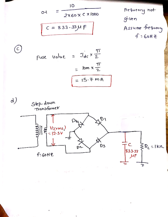
1. Power supply (ac to dc) design. [10 pts.] Design a full-wave bridge rectifier circuit to deliv...
A) Draw the circuit diagram and design a half wave rectifier AC-DC converter to deliver 12V-DC...
A) Draw the circuit diagram and design a half wave rectifier AC-DC converter to deliver 12V-DC with a ripple of 10 mV for a load current of 0.5 A - Design means to find the capacitor value and the ratio of the turns in the transformer assuume the supply voltage is 120v and 60Hz B) Calculate the Peak Inverse Voltage, average and max current through the diode.
Design a FULL WAVE BRIDGE RECTIFIER circuit that will: Take 120volts ac, 60 hz, sinusoidal wavef...
Design a FULL WAVE BRIDGE RECTIFIER circuit that will: Take 120volts ac, 60 hz, sinusoidal waveform from the wall power and convert it to a “regulated” dc value giving 15 volts +, - 1.0 volts across a 1200-ohm output load resistor with no more than 2% ripple voltage, all at a total component parts cost of less than $175.00 (US$). Your design process/ analysis is to be conducted by hand. Consider for this design task: Assume an ideal transformer and...
Q4. Most electronic systems need a dc voltage to work properly. The AC-to-DC power supply system ...
 part g
Q4. Most electronic systems need a dc voltage to work properly. The AC-to-DC power supply system is including a transformer, a rectifier and a capacitor input filter. The AC input voltage is 110 Vrms at 60 Hz. (a) Draw the full wave bridge rectifier circuit with transformer which steps down voltage to safer and lower levels that are more suitable for use with diodes (b) Show how the capacitor input filter connects to the rectifier output in the...
part g
Q4. Most electronic systems need a dc voltage to work properly. The AC-to-DC power supply system is including a transformer, a rectifier and a capacitor input filter. The AC input voltage is 110 Vrms at 60 Hz. (a) Draw the full wave bridge rectifier circuit with transformer which steps down voltage to safer and lower levels that are more suitable for use with diodes (b) Show how the capacitor input filter connects to the rectifier output in the...
Design a FULL WAVE BRIDGE RECTIFIER circuit that will: Take 120volts ac, 60 hz, sinusoidal waveform...
 Design a FULL WAVE BRIDGE RECTIFIER circuit that will:
Take 120volts ac, 60 hz, sinusoidal waveform and convert
it to a “regulated “dc value
giving 12 volts +, - 1 volt across a 2000-ohm output
load resistor with no more than 2%
ripple voltage.
You may assume:
a. An ideal power transformer as discussed in class.
b. For hand computations, you must assume a diode given by
Figure 4.8 page 185.
c. A filter capacitor sized per the textbook equation...
Design a FULL WAVE BRIDGE RECTIFIER circuit that will:
Take 120volts ac, 60 hz, sinusoidal waveform and convert
it to a “regulated “dc value
giving 12 volts +, - 1 volt across a 2000-ohm output
load resistor with no more than 2%
ripple voltage.
You may assume:
a. An ideal power transformer as discussed in class.
b. For hand computations, you must assume a diode given by
Figure 4.8 page 185.
c. A filter capacitor sized per the textbook equation...
design bridge rectifier connected to ac mains to produce an output of 10 volt dc having...
design bridge rectifier connected to ac mains to produce an output of 10 volt dc having a ripple voltage <0.5 v
3. Consider the full-wave bridge rectifier circuit shown below. The full-wave bridge is made using silicon...
 3. Consider the full-wave bridge rectifier circuit shown below. The full-wave bridge is made using silicon diodes. 120V 15V 120 V(ms) n 60 Hz 752 Vout a. Find the maximum value of VoUT, and the voltage rating for the capacitor assuming a 50% margin of safety. b. Choose the capacitance of the filter capacitor for a peak-to-peak ripple of 1V, and determine the corresponding peak diode current. What is the frequency of the ripple voltage? c. Now suppose the filter...
Question 4. (a) A full-wave bridge rectifier power supply is powered from the secondary of a...
 Question 4. (a) A full-wave bridge rectifier power supply is powered from the secondary of a transformer which has a rms secondary voltage of 15.6V. The primary of the transformer is connected to a 50Hz, 230VRMS power supply. A 2700uF filter capacitor is used. A current of 1.5 Amp is drawn from the supply. (i) Sketch a schematic diagram of the setup. (ii) Calculate the mean de output voltage. Assume each power diode has a forward voltage drop of 1...
You need to design a DC power supply that provides an average DC output voltage of...
 You need to design a DC power supply that provides an average DC output voltage of 5V to charge your cellphone. The maximum allowed ripple at the output is ±200 mV. Your cellphone can be modeled as a 1 50Ω load. You have to use a bridge rectifier with four diodes. Note: For calculations, consider constant voltage drop model of the diode with V0 = 0.7V. (a) The charger is designed to use in the US, i.e. transformer primary is...
D *4.80 It is required to use a peak rectifier to design a de power supply...
 D *4.80 It is required to use a peak rectifier to design a de power supply that provides an average de output voltage of 12 V on which a maximum of ±1-V ripple is allowed. The rectifier feeds a load of 200 2. The rectifier is fed from the line voltage (120 V rms, 60 Hz) through a transformer. The diodes available have 0.7-V drop when conducting. If the designer opts for the half-wave circuit: (a) Specify the rms voltage...
Capacitor is connected to secondary (1) A fullwave bridge rectifier power supply is powered from the secondary of a transformer which has a peak secondary voltage of 22V. The primary of the transforme...
 Capacitor
is connected to secondary
(1) A fullwave bridge rectifier power supply is powered from the secondary of a transformer which has a peak secondary voltage of 22V. The primary of the transformer is connected to a 50Hz, 230Vus power supply. A 2700μF filter capacitor is used. A current of 1.5 Amp is drawn from the supply (i) Sketch a schematic diagram of the setup (ii) Calculate the mean dc output voltage (ii) Assume that each diode conducts for one-twelfth...
Capacitor
is connected to secondary
(1) A fullwave bridge rectifier power supply is powered from the secondary of a transformer which has a peak secondary voltage of 22V. The primary of the transformer is connected to a 50Hz, 230Vus power supply. A 2700μF filter capacitor is used. A current of 1.5 Amp is drawn from the supply (i) Sketch a schematic diagram of the setup (ii) Calculate the mean dc output voltage (ii) Assume that each diode conducts for one-twelfth...
 part g
Q4. Most electronic systems need a dc voltage to work properly. The AC-to-DC power supply system is including a transformer, a rectifier and a capacitor input filter. The AC input voltage is 110 Vrms at 60 Hz. (a) Draw the full wave bridge rectifier circuit with transformer which steps down voltage to safer and lower levels that are more suitable for use with diodes (b) Show how the capacitor input filter connects to the rectifier output in the...
part g
Q4. Most electronic systems need a dc voltage to work properly. The AC-to-DC power supply system is including a transformer, a rectifier and a capacitor input filter. The AC input voltage is 110 Vrms at 60 Hz. (a) Draw the full wave bridge rectifier circuit with transformer which steps down voltage to safer and lower levels that are more suitable for use with diodes (b) Show how the capacitor input filter connects to the rectifier output in the...
 Design a FULL WAVE BRIDGE RECTIFIER circuit that will:
Take 120volts ac, 60 hz, sinusoidal waveform and convert
it to a “regulated “dc value
giving 12 volts +, - 1 volt across a 2000-ohm output
load resistor with no more than 2%
ripple voltage.
You may assume:
a. An ideal power transformer as discussed in class.
b. For hand computations, you must assume a diode given by
Figure 4.8 page 185.
c. A filter capacitor sized per the textbook equation...
Design a FULL WAVE BRIDGE RECTIFIER circuit that will:
Take 120volts ac, 60 hz, sinusoidal waveform and convert
it to a “regulated “dc value
giving 12 volts +, - 1 volt across a 2000-ohm output
load resistor with no more than 2%
ripple voltage.
You may assume:
a. An ideal power transformer as discussed in class.
b. For hand computations, you must assume a diode given by
Figure 4.8 page 185.
c. A filter capacitor sized per the textbook equation...
 3. Consider the full-wave bridge rectifier circuit shown below. The full-wave bridge is made using silicon diodes. 120V 15V 120 V(ms) n 60 Hz 752 Vout a. Find the maximum value of VoUT, and the voltage rating for the capacitor assuming a 50% margin of safety. b. Choose the capacitance of the filter capacitor for a peak-to-peak ripple of 1V, and determine the corresponding peak diode current. What is the frequency of the ripple voltage? c. Now suppose the filter...
 Question 4. (a) A full-wave bridge rectifier power supply is powered from the secondary of a transformer which has a rms secondary voltage of 15.6V. The primary of the transformer is connected to a 50Hz, 230VRMS power supply. A 2700uF filter capacitor is used. A current of 1.5 Amp is drawn from the supply. (i) Sketch a schematic diagram of the setup. (ii) Calculate the mean de output voltage. Assume each power diode has a forward voltage drop of 1...
 You need to design a DC power supply that provides an average DC output voltage of 5V to charge your cellphone. The maximum allowed ripple at the output is ±200 mV. Your cellphone can be modeled as a 1 50Ω load. You have to use a bridge rectifier with four diodes. Note: For calculations, consider constant voltage drop model of the diode with V0 = 0.7V. (a) The charger is designed to use in the US, i.e. transformer primary is...
 D *4.80 It is required to use a peak rectifier to design a de power supply that provides an average de output voltage of 12 V on which a maximum of ±1-V ripple is allowed. The rectifier feeds a load of 200 2. The rectifier is fed from the line voltage (120 V rms, 60 Hz) through a transformer. The diodes available have 0.7-V drop when conducting. If the designer opts for the half-wave circuit: (a) Specify the rms voltage...
 Capacitor
is connected to secondary
(1) A fullwave bridge rectifier power supply is powered from the secondary of a transformer which has a peak secondary voltage of 22V. The primary of the transformer is connected to a 50Hz, 230Vus power supply. A 2700μF filter capacitor is used. A current of 1.5 Amp is drawn from the supply (i) Sketch a schematic diagram of the setup (ii) Calculate the mean dc output voltage (ii) Assume that each diode conducts for one-twelfth...
Capacitor
is connected to secondary
(1) A fullwave bridge rectifier power supply is powered from the secondary of a transformer which has a peak secondary voltage of 22V. The primary of the transformer is connected to a 50Hz, 230Vus power supply. A 2700μF filter capacitor is used. A current of 1.5 Amp is drawn from the supply (i) Sketch a schematic diagram of the setup (ii) Calculate the mean dc output voltage (ii) Assume that each diode conducts for one-twelfth...
Most questions answered within 3 hours.
-
A box contains 14 large marbles and 19 small marbles. Each
marble is either green or...
asked 1 minute ago -
The results of a one-sample t test were t (18) = 2.11,
p < 0.05. In...
asked 11 minutes ago -
What kind of share-based compensation does the company have for
Verizon? What was compensation expense for...
asked 19 minutes ago -
Place each of the following transactions in one of the four
components of expenditure: (remember it...
asked 27 minutes ago -
Find the optimal binary symbol code using the Huffman coding
algorithm. Draw the Huffman tree (show...
asked 30 minutes ago -
Using Rhodes Corporation’s financial statements (shown after
part f), answer the following questions.
a. What is...
asked 30 minutes ago -
Viewers of the ABC news segment may use ___________ to make
generalization about what the individual...
asked 39 minutes ago -
Which of the following captures Locke’s response to Hobbes on
the issue of the enforcement of...
asked 47 minutes ago -
another 515 students are selected at random from florida. they are
given a 3-hour preparation course...
asked 1 hour ago -
A regional distributor deals with a product ABC that has an
annual demand of 3000 unit....
asked 1 hour ago -
You have a 825.3 mL sample of 2.754 M HA (Ka =
4.49⋅10−4). Calculate the pH...
asked 5 hours ago -
The blues made its way into many kinds of music. Eric Clapton,
The Beatles, and Elvis...
asked 7 hours ago