

 Capacitor
is connected to secondary
Capacitor
is connected to secondary
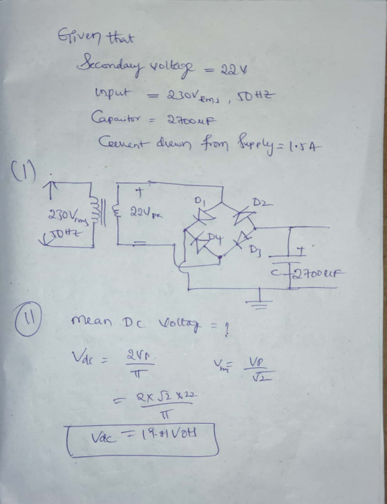
transformer is connected to a 50Hz, 230Vus power supply. A 2700μF filter capacitor is used. A current of 1.5 Amp is drawn from the supply (i) Sketch a schematic diagram of the setup (ii) Calculate the mean dc output voltage
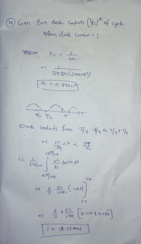
(ii) Assume that each diode conducts for one-twelfth (1/12h) of a cycle. What is the mean diode current while each is conducting? (iv) What would happen to the mean diode current you calculated in (iii) if a smaller filter capacitance was used in your circuit? Give a reason for your answer
Homework Answers

Kindly upvote if it's helpful for you.
Add Answer to:
Capacitor is connected to secondary (1) A fullwave bridge rectifier power supply is powered from the secondary of a transformer which has a peak secondary voltage of 22V. The primary of the transforme...
Question 4. (a) A full-wave bridge rectifier power supply is powered from the secondary of a...
 Question 4. (a) A full-wave bridge rectifier power supply is powered from the secondary of a transformer which has a rms secondary voltage of 15.6V. The primary of the transformer is connected to a 50Hz, 230VRMS power supply. A 2700uF filter capacitor is used. A current of 1.5 Amp is drawn from the supply. (i) Sketch a schematic diagram of the setup. (ii) Calculate the mean de output voltage. Assume each power diode has a forward voltage drop of 1...
Q4. Most electronic systems need a dc voltage to work properly. The AC-to-DC power supply system ...
 part g
Q4. Most electronic systems need a dc voltage to work properly. The AC-to-DC power supply system is including a transformer, a rectifier and a capacitor input filter. The AC input voltage is 110 Vrms at 60 Hz. (a) Draw the full wave bridge rectifier circuit with transformer which steps down voltage to safer and lower levels that are more suitable for use with diodes (b) Show how the capacitor input filter connects to the rectifier output in the...
part g
Q4. Most electronic systems need a dc voltage to work properly. The AC-to-DC power supply system is including a transformer, a rectifier and a capacitor input filter. The AC input voltage is 110 Vrms at 60 Hz. (a) Draw the full wave bridge rectifier circuit with transformer which steps down voltage to safer and lower levels that are more suitable for use with diodes (b) Show how the capacitor input filter connects to the rectifier output in the...
Question 1 (25 marks) a) A full wave rectifier has 40V peak secondary voltage, 2,000uF capacitor...
 Question 1 (25 marks) a) A full wave rectifier has 40V peak secondary voltage, 2,000uF capacitor and 1022 load. You may take the line frequency as 50Hz and voltage drop across a diode as 0.7V. i. Calculate the peak dc voltage (VA). (2 marks) ii. Calculate the dc load voltage (Vdcloed). (4 marks) iii. Calculate the ripple voltage (AVLoad). (4 marks) b) The capacitance, inductance and load resistance of a Buck step-down dc-to-dc converter are 1.0uF, 10uH and 20.022 respectively....
1) What component in a power supply converts ac line voltage to dc voltage? a. Transformer...
1) What component in a power supply converts ac line voltage to dc voltage? a. Transformer b. rectifier diode c. resistor d. capacitor 2) A circuit that provides an entirely positive or negative output voltage when an ac input voltage is applied is called a a. rectifier b. inverter c. filter capacitor d. zener diode 3) A control voltage or current is the a. power factor b. bias c. ground d. load 4) When the voltage at the op amp's...
D *4.80 It is required to use a peak rectifier to design a de power supply...
 D *4.80 It is required to use a peak rectifier to design a de power supply that provides an average de output voltage of 12 V on which a maximum of ±1-V ripple is allowed. The rectifier feeds a load of 200 2. The rectifier is fed from the line voltage (120 V rms, 60 Hz) through a transformer. The diodes available have 0.7-V drop when conducting. If the designer opts for the half-wave circuit: (a) Specify the rms voltage...
1. Power supply (ac to dc) design. [10 pts.] Design a full-wave bridge rectifier circuit to deliv...
 1. Power supply (ac to dc) design. [10 pts.] Design a full-wave bridge rectifier circuit to deliver 10 volts dc with less than 0.1 volt (peak to peak) ripple into a load drawing up to 10 mA. (a) Choose the appropriate ac input voltage from the transformer secondary assuming the usual voltage drops for silicon diodes. (b) Determine the correct capacitor value to ensure the specified ripple in your calculation (c) What fuse value should you select for the primary...
You need to design a DC power supply that provides an average DC output voltage of...
 You need to design a DC power supply that provides an average DC output voltage of 5V to charge your cellphone. The maximum allowed ripple at the output is ±200 mV. Your cellphone can be modeled as a 1 50Ω load. You have to use a bridge rectifier with four diodes. Note: For calculations, consider constant voltage drop model of the diode with V0 = 0.7V. (a) The charger is designed to use in the US, i.e. transformer primary is...
How can a center-tapped power transformer be used with a bridge rectifier to produce a power...
How can a center-tapped power transformer be used with a bridge rectifier to produce a power supply that provides both a positive and negative DC voltage?
In this part of the term paper, design a single-phase switch-mode DC power supply with a forward ...
 In this part of the term paper, design a single-phase switch-mode DC power supply with a forward converter. Provide answers to the questions below Please combine the single-phase full-wave rectifier from part two of your term paper with a forward converter to produce a switch-mode DC power supply, as shown below. The output of the bridge rectifier serves as input to the forward converter L1 Np: N BH621BH62 D, V1 Load C1 100p 45 Vrms D3 BH62 18H62 D4 Control...
1. (10 PT) A three-phase bridge rectifier circuit shown in the figure phase voltage of 220 volts rms. A load of 100 Ω is connected across is supplied by a rectifier. Both the primary and secondary...
 1. (10 PT) A three-phase bridge rectifier circuit shown in the figure phase voltage of 220 volts rms. A load of 100 Ω is connected across is supplied by a rectifier. Both the primary and secondary windings of transfor Assume the transformer has a turns ratio of unity mer are Y-connected a) 3 PTI On the top of voltage plot on next page indicate the diodes that will be conducting during different intervals of time. b) 17 PT] Plot the...
 Question 4. (a) A full-wave bridge rectifier power supply is powered from the secondary of a transformer which has a rms secondary voltage of 15.6V. The primary of the transformer is connected to a 50Hz, 230VRMS power supply. A 2700uF filter capacitor is used. A current of 1.5 Amp is drawn from the supply. (i) Sketch a schematic diagram of the setup. (ii) Calculate the mean de output voltage. Assume each power diode has a forward voltage drop of 1...
 part g
Q4. Most electronic systems need a dc voltage to work properly. The AC-to-DC power supply system is including a transformer, a rectifier and a capacitor input filter. The AC input voltage is 110 Vrms at 60 Hz. (a) Draw the full wave bridge rectifier circuit with transformer which steps down voltage to safer and lower levels that are more suitable for use with diodes (b) Show how the capacitor input filter connects to the rectifier output in the...
part g
Q4. Most electronic systems need a dc voltage to work properly. The AC-to-DC power supply system is including a transformer, a rectifier and a capacitor input filter. The AC input voltage is 110 Vrms at 60 Hz. (a) Draw the full wave bridge rectifier circuit with transformer which steps down voltage to safer and lower levels that are more suitable for use with diodes (b) Show how the capacitor input filter connects to the rectifier output in the...
 Question 1 (25 marks) a) A full wave rectifier has 40V peak secondary voltage, 2,000uF capacitor and 1022 load. You may take the line frequency as 50Hz and voltage drop across a diode as 0.7V. i. Calculate the peak dc voltage (VA). (2 marks) ii. Calculate the dc load voltage (Vdcloed). (4 marks) iii. Calculate the ripple voltage (AVLoad). (4 marks) b) The capacitance, inductance and load resistance of a Buck step-down dc-to-dc converter are 1.0uF, 10uH and 20.022 respectively....
 D *4.80 It is required to use a peak rectifier to design a de power supply that provides an average de output voltage of 12 V on which a maximum of ±1-V ripple is allowed. The rectifier feeds a load of 200 2. The rectifier is fed from the line voltage (120 V rms, 60 Hz) through a transformer. The diodes available have 0.7-V drop when conducting. If the designer opts for the half-wave circuit: (a) Specify the rms voltage...
 1. Power supply (ac to dc) design. [10 pts.] Design a full-wave bridge rectifier circuit to deliver 10 volts dc with less than 0.1 volt (peak to peak) ripple into a load drawing up to 10 mA. (a) Choose the appropriate ac input voltage from the transformer secondary assuming the usual voltage drops for silicon diodes. (b) Determine the correct capacitor value to ensure the specified ripple in your calculation (c) What fuse value should you select for the primary...
 You need to design a DC power supply that provides an average DC output voltage of 5V to charge your cellphone. The maximum allowed ripple at the output is ±200 mV. Your cellphone can be modeled as a 1 50Ω load. You have to use a bridge rectifier with four diodes. Note: For calculations, consider constant voltage drop model of the diode with V0 = 0.7V. (a) The charger is designed to use in the US, i.e. transformer primary is...
 In this part of the term paper, design a single-phase switch-mode DC power supply with a forward converter. Provide answers to the questions below Please combine the single-phase full-wave rectifier from part two of your term paper with a forward converter to produce a switch-mode DC power supply, as shown below. The output of the bridge rectifier serves as input to the forward converter L1 Np: N BH621BH62 D, V1 Load C1 100p 45 Vrms D3 BH62 18H62 D4 Control...
 1. (10 PT) A three-phase bridge rectifier circuit shown in the figure phase voltage of 220 volts rms. A load of 100 Ω is connected across is supplied by a rectifier. Both the primary and secondary windings of transfor Assume the transformer has a turns ratio of unity mer are Y-connected a) 3 PTI On the top of voltage plot on next page indicate the diodes that will be conducting during different intervals of time. b) 17 PT] Plot the...
Most questions answered within 3 hours.
-
An isolated colony represents a pure culture. one rare occasions
, however , a colony can...
asked 11 minutes ago -
*****DO NOT ANSWER THIS QUESTION IF YOU DON'T
KNOW*******Rights and Duties of Auditors; Minimum 4000
words...
asked 1 hour ago -
The probability that Janie is wearing sunglasses is 1/4. The
probability that she is wearing sunglasses...
asked 1 hour ago -
Do you believe social media is more of a help or a hindrance in
controlling crises...
asked 1 hour ago -
Two long, parallel wires separated by 2.85 cm carry currents in
opposite directions. The current in...
asked 1 hour ago -
Question # 1. Develop a list of rehabilitation journals
that publish articles concerning career counseling for...
asked 1 hour ago -
Bryant Company has a factory machine with a book value of
$85,100 and a remaining useful...
asked 1 hour ago -
What is the default classification for federal tax purposes of a
U.S. eligible entity with one...
asked 1 hour ago -
1. How many grams would 4.0x10²¹ atoms of calcium
weigh?
2.. Calculate the percent oxygen in...
asked 1 hour ago -
Balance Equation
K2Cr2O7 + H2C2O4 2H2O 6 K[Cr(C2O4 )2 (H2O)2 ]2H2O + CO2 +
H2O
asked 1 hour ago -
Select a position in the clinical laboratory and write an
appropriate job description and corresponding work...
asked 2 hours ago -
Targeting the Bottom of the Pyramid
What are some of the broader societal pricing concerns faced...
asked 2 hours ago