See attached. Please show all steps clearly!

Homework Answers

Add Answer to:
See attached. Please show all steps clearly!
QUESTION 1 The voltage produced by the source is...
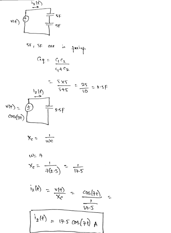
Please write clearly, and show steps for the solution (The answers are shown just to check)...
 Please write clearly, and show steps for the solution
(The answers are shown just to check)
6. For the circuit shown, the voltage source supplies a voltage v(t)= 20 cos(1000t) V. a) Find the equivalent impedance Z as seen by the voltage source. Ans: 2.4 + 214.8 i(t) ► 10mH 0000 b) Determine i(t), and the voltage across the 10 mH inductor. i(t) = 1.33 cos(1000t - 80.8) Find the voltage across the resistor as a function of time. v(t)...
Please write clearly, and show steps for the solution
(The answers are shown just to check)
6. For the circuit shown, the voltage source supplies a voltage v(t)= 20 cos(1000t) V. a) Find the equivalent impedance Z as seen by the voltage source. Ans: 2.4 + 214.8 i(t) ► 10mH 0000 b) Determine i(t), and the voltage across the 10 mH inductor. i(t) = 1.33 cos(1000t - 80.8) Find the voltage across the resistor as a function of time. v(t)...
Please show all work clearly with the answer. Thank you! A voltage (in volts) is given...
 Please show all work clearly with the answer.
Thank you!
A voltage (in volts) is given by u(t) 12 cos 200t-5 sin 200t Express the voltage as (a) a cosine function and (b) a sine function.
Please show all work clearly with the answer.
Thank you!
A voltage (in volts) is given by u(t) 12 cos 200t-5 sin 200t Express the voltage as (a) a cosine function and (b) a sine function.
Please help with number 1. 1 SECTION - A Question 1 - DC Circuits and DC...
 Please help with number 1. 1
SECTION - A Question 1 - DC Circuits and DC Transients [25] After having been open for a very long time, the switch in the circuit shown in Figure 1 is closed at t= 0. Cat Find the currents 11, 12 and is immediately after the switch has been closed. 61 Find the equivalent resistance after the switch is closed and determine the time constant of the circuit. 0 Determine the mathematical expressions for...
Please help with number 1. 1
SECTION - A Question 1 - DC Circuits and DC Transients [25] After having been open for a very long time, the switch in the circuit shown in Figure 1 is closed at t= 0. Cat Find the currents 11, 12 and is immediately after the switch has been closed. 61 Find the equivalent resistance after the switch is closed and determine the time constant of the circuit. 0 Determine the mathematical expressions for...
Hello Please write clearly and visible large print is good. Please explain all steps chosen, and...
 Hello Please write clearly and visible large
print is good. Please explain all steps chosen, and use best
practices, or common methods to solve. Please, and thank you
I will rate up.
10. + -/2 points My Notes + Ask Your Teacher In this circuit, the sources have values Vsi(t) = 24 · cos(1900 · t) V and Vs2(t) = 12 · cos(1900 · t + 35°) V, while the components have values R = 3.2 k22, L1 = 4.2...
Hello Please write clearly and visible large
print is good. Please explain all steps chosen, and use best
practices, or common methods to solve. Please, and thank you
I will rate up.
10. + -/2 points My Notes + Ask Your Teacher In this circuit, the sources have values Vsi(t) = 24 · cos(1900 · t) V and Vs2(t) = 12 · cos(1900 · t + 35°) V, while the components have values R = 3.2 k22, L1 = 4.2...
Show a sketch clearly labeling all of the voltages and currents, and determine the governing differential...
 Show a sketch clearly labeling all of the voltages and
currents, and determine the governing differential equation as
indicated.
please show steps
6. The electro-mechanical system shown below consists of an electric motor with input voltage V which drives inertia I in the mechanical system (see torque T). Find the governing differential equations of motion for this electro-mechanical system in terms of the input voltage to the motor and output displacement y. Electrical System Vbas -Motor Motor Input Voltage bMotor...
Show a sketch clearly labeling all of the voltages and
currents, and determine the governing differential equation as
indicated.
please show steps
6. The electro-mechanical system shown below consists of an electric motor with input voltage V which drives inertia I in the mechanical system (see torque T). Find the governing differential equations of motion for this electro-mechanical system in terms of the input voltage to the motor and output displacement y. Electrical System Vbas -Motor Motor Input Voltage bMotor...
Please solve both 1 and 2, include all steps so i can follow clearly and understand...
 Please solve both 1 and 2,
include all steps so i can follow clearly and understand the
problem thank you
1. (A) Find the Thevenin equivalent circuit for the portion of the circuit below which includes all of the components except the 5k resistor on the far right. (B) Now find the current through the 5k resistor using your Thevenin equivalent from part A 2k lk 5k 1k 2k 2. Test reciprocity with a current source and voltage measurement by...
Please solve both 1 and 2,
include all steps so i can follow clearly and understand the
problem thank you
1. (A) Find the Thevenin equivalent circuit for the portion of the circuit below which includes all of the components except the 5k resistor on the far right. (B) Now find the current through the 5k resistor using your Thevenin equivalent from part A 2k lk 5k 1k 2k 2. Test reciprocity with a current source and voltage measurement by...
Please answer the following question! Please write CLEARLY, showing all steps, and follow all steps Please...
 Please answer the following question!
Please write CLEARLY, showing all steps, and follow all
steps
Please box final answer. Please do not copy anothers work.
3. For each of the circuits shown in Fig. P5.57, find the labeled node voltages. The NMOS transistors have Vtn = 0.9V, ka 6,-) = 1.5m A/V2.(20 points) +5V +5V +2.5 V ZIKA UL 21 ξΙΚΩ -2.5 V Willie (a) Fig. P5.57
Please answer the following question!
Please write CLEARLY, showing all steps, and follow all
steps
Please box final answer. Please do not copy anothers work.
3. For each of the circuits shown in Fig. P5.57, find the labeled node voltages. The NMOS transistors have Vtn = 0.9V, ka 6,-) = 1.5m A/V2.(20 points) +5V +5V +2.5 V ZIKA UL 21 ξΙΚΩ -2.5 V Willie (a) Fig. P5.57
please answer all questions and show all steps 5) The voltage source V, below has a...
 please answer all questions and show all steps
5) The voltage source V, below has a frequency of 60Hz. The load is operating at 10kVA with 0.8pf leading. The angle of the voltage across the load is 0 degrees. Assume all values are RMS. Is 0.12 500uH - 120V V eterm: Please determine the following a) The phasor Is b) The power loss in the transmission line. c) The phasor Vs d) The component (inductor or capacitor) that must be...
please answer all questions and show all steps
5) The voltage source V, below has a frequency of 60Hz. The load is operating at 10kVA with 0.8pf leading. The angle of the voltage across the load is 0 degrees. Assume all values are RMS. Is 0.12 500uH - 120V V eterm: Please determine the following a) The phasor Is b) The power loss in the transmission line. c) The phasor Vs d) The component (inductor or capacitor) that must be...
Electric circuit problem Please answers with detailed steps in understandable handwriting Problem 2. A voltage source...
 Electric circuit problem
Please answers with detailed steps in understandable
handwriting
Problem 2. A voltage source is connected to a 300 nF capacitor. The voltage v(t) is given by: (2 tv, Osts 6s v(t) = 2 (t – 12)2V, 65ts 12s 0, otherise a. Find an expression for the current through the capacitor b. Sketch (or plot using a computer) the voltage and current from 0 to 12 s. (If you use Matlab please include a listing of your Matlab...
Electric circuit problem
Please answers with detailed steps in understandable
handwriting
Problem 2. A voltage source is connected to a 300 nF capacitor. The voltage v(t) is given by: (2 tv, Osts 6s v(t) = 2 (t – 12)2V, 65ts 12s 0, otherise a. Find an expression for the current through the capacitor b. Sketch (or plot using a computer) the voltage and current from 0 to 12 s. (If you use Matlab please include a listing of your Matlab...
Please show all steps. This question makes no sense to me We were unable to transcribe...
 Please show all steps. This question makes no sense to
me
We were unable to transcribe this imageFind the currents through each resistor in the circuit shown on the diagram (Figure 1). Use the following values: E = 12.0 V , R = 35.0 12, R2 = 22.0 2, R3 = 41.0 N, and R. = 14.0 12
Please show all steps. This question makes no sense to
me
We were unable to transcribe this imageFind the currents through each resistor in the circuit shown on the diagram (Figure 1). Use the following values: E = 12.0 V , R = 35.0 12, R2 = 22.0 2, R3 = 41.0 N, and R. = 14.0 12
 Please write clearly, and show steps for the solution
(The answers are shown just to check)
6. For the circuit shown, the voltage source supplies a voltage v(t)= 20 cos(1000t) V. a) Find the equivalent impedance Z as seen by the voltage source. Ans: 2.4 + 214.8 i(t) ► 10mH 0000 b) Determine i(t), and the voltage across the 10 mH inductor. i(t) = 1.33 cos(1000t - 80.8) Find the voltage across the resistor as a function of time. v(t)...
Please write clearly, and show steps for the solution
(The answers are shown just to check)
6. For the circuit shown, the voltage source supplies a voltage v(t)= 20 cos(1000t) V. a) Find the equivalent impedance Z as seen by the voltage source. Ans: 2.4 + 214.8 i(t) ► 10mH 0000 b) Determine i(t), and the voltage across the 10 mH inductor. i(t) = 1.33 cos(1000t - 80.8) Find the voltage across the resistor as a function of time. v(t)...
 Please show all work clearly with the answer.
Thank you!
A voltage (in volts) is given by u(t) 12 cos 200t-5 sin 200t Express the voltage as (a) a cosine function and (b) a sine function.
Please show all work clearly with the answer.
Thank you!
A voltage (in volts) is given by u(t) 12 cos 200t-5 sin 200t Express the voltage as (a) a cosine function and (b) a sine function.
 Please help with number 1. 1
SECTION - A Question 1 - DC Circuits and DC Transients [25] After having been open for a very long time, the switch in the circuit shown in Figure 1 is closed at t= 0. Cat Find the currents 11, 12 and is immediately after the switch has been closed. 61 Find the equivalent resistance after the switch is closed and determine the time constant of the circuit. 0 Determine the mathematical expressions for...
Please help with number 1. 1
SECTION - A Question 1 - DC Circuits and DC Transients [25] After having been open for a very long time, the switch in the circuit shown in Figure 1 is closed at t= 0. Cat Find the currents 11, 12 and is immediately after the switch has been closed. 61 Find the equivalent resistance after the switch is closed and determine the time constant of the circuit. 0 Determine the mathematical expressions for...
 Hello Please write clearly and visible large
print is good. Please explain all steps chosen, and use best
practices, or common methods to solve. Please, and thank you
I will rate up.
10. + -/2 points My Notes + Ask Your Teacher In this circuit, the sources have values Vsi(t) = 24 · cos(1900 · t) V and Vs2(t) = 12 · cos(1900 · t + 35°) V, while the components have values R = 3.2 k22, L1 = 4.2...
Hello Please write clearly and visible large
print is good. Please explain all steps chosen, and use best
practices, or common methods to solve. Please, and thank you
I will rate up.
10. + -/2 points My Notes + Ask Your Teacher In this circuit, the sources have values Vsi(t) = 24 · cos(1900 · t) V and Vs2(t) = 12 · cos(1900 · t + 35°) V, while the components have values R = 3.2 k22, L1 = 4.2...
 Show a sketch clearly labeling all of the voltages and
currents, and determine the governing differential equation as
indicated.
please show steps
6. The electro-mechanical system shown below consists of an electric motor with input voltage V which drives inertia I in the mechanical system (see torque T). Find the governing differential equations of motion for this electro-mechanical system in terms of the input voltage to the motor and output displacement y. Electrical System Vbas -Motor Motor Input Voltage bMotor...
Show a sketch clearly labeling all of the voltages and
currents, and determine the governing differential equation as
indicated.
please show steps
6. The electro-mechanical system shown below consists of an electric motor with input voltage V which drives inertia I in the mechanical system (see torque T). Find the governing differential equations of motion for this electro-mechanical system in terms of the input voltage to the motor and output displacement y. Electrical System Vbas -Motor Motor Input Voltage bMotor...
 Please solve both 1 and 2,
include all steps so i can follow clearly and understand the
problem thank you
1. (A) Find the Thevenin equivalent circuit for the portion of the circuit below which includes all of the components except the 5k resistor on the far right. (B) Now find the current through the 5k resistor using your Thevenin equivalent from part A 2k lk 5k 1k 2k 2. Test reciprocity with a current source and voltage measurement by...
Please solve both 1 and 2,
include all steps so i can follow clearly and understand the
problem thank you
1. (A) Find the Thevenin equivalent circuit for the portion of the circuit below which includes all of the components except the 5k resistor on the far right. (B) Now find the current through the 5k resistor using your Thevenin equivalent from part A 2k lk 5k 1k 2k 2. Test reciprocity with a current source and voltage measurement by...
 Please answer the following question!
Please write CLEARLY, showing all steps, and follow all
steps
Please box final answer. Please do not copy anothers work.
3. For each of the circuits shown in Fig. P5.57, find the labeled node voltages. The NMOS transistors have Vtn = 0.9V, ka 6,-) = 1.5m A/V2.(20 points) +5V +5V +2.5 V ZIKA UL 21 ξΙΚΩ -2.5 V Willie (a) Fig. P5.57
Please answer the following question!
Please write CLEARLY, showing all steps, and follow all
steps
Please box final answer. Please do not copy anothers work.
3. For each of the circuits shown in Fig. P5.57, find the labeled node voltages. The NMOS transistors have Vtn = 0.9V, ka 6,-) = 1.5m A/V2.(20 points) +5V +5V +2.5 V ZIKA UL 21 ξΙΚΩ -2.5 V Willie (a) Fig. P5.57
 please answer all questions and show all steps
5) The voltage source V, below has a frequency of 60Hz. The load is operating at 10kVA with 0.8pf leading. The angle of the voltage across the load is 0 degrees. Assume all values are RMS. Is 0.12 500uH - 120V V eterm: Please determine the following a) The phasor Is b) The power loss in the transmission line. c) The phasor Vs d) The component (inductor or capacitor) that must be...
please answer all questions and show all steps
5) The voltage source V, below has a frequency of 60Hz. The load is operating at 10kVA with 0.8pf leading. The angle of the voltage across the load is 0 degrees. Assume all values are RMS. Is 0.12 500uH - 120V V eterm: Please determine the following a) The phasor Is b) The power loss in the transmission line. c) The phasor Vs d) The component (inductor or capacitor) that must be...
 Electric circuit problem
Please answers with detailed steps in understandable
handwriting
Problem 2. A voltage source is connected to a 300 nF capacitor. The voltage v(t) is given by: (2 tv, Osts 6s v(t) = 2 (t – 12)2V, 65ts 12s 0, otherise a. Find an expression for the current through the capacitor b. Sketch (or plot using a computer) the voltage and current from 0 to 12 s. (If you use Matlab please include a listing of your Matlab...
Electric circuit problem
Please answers with detailed steps in understandable
handwriting
Problem 2. A voltage source is connected to a 300 nF capacitor. The voltage v(t) is given by: (2 tv, Osts 6s v(t) = 2 (t – 12)2V, 65ts 12s 0, otherise a. Find an expression for the current through the capacitor b. Sketch (or plot using a computer) the voltage and current from 0 to 12 s. (If you use Matlab please include a listing of your Matlab...
 Please show all steps. This question makes no sense to
me
We were unable to transcribe this imageFind the currents through each resistor in the circuit shown on the diagram (Figure 1). Use the following values: E = 12.0 V , R = 35.0 12, R2 = 22.0 2, R3 = 41.0 N, and R. = 14.0 12
Please show all steps. This question makes no sense to
me
We were unable to transcribe this imageFind the currents through each resistor in the circuit shown on the diagram (Figure 1). Use the following values: E = 12.0 V , R = 35.0 12, R2 = 22.0 2, R3 = 41.0 N, and R. = 14.0 12
Most questions answered within 3 hours.
-
Angel Corporation has $10,000,000 of
8.0% 25 year bonds dated May 1, 2018 with interest payable...
asked 16 minutes ago -
7.
________ involves individuals trading goods they already have or
providing services in exchange for something...
asked 20 minutes ago -
Share your research problem. What databases did you search as
you gathered evidence to support your...
asked 20 minutes ago -
what process occurs to form microspores and megaspores in flowering
plants?
asked 28 minutes ago -
C++
I need to use the function getData to put in all my data using
arrays....
asked 27 minutes ago -
A block is hung by a string from the inside roof of a van. When
the...
asked 34 minutes ago -
Do you think companies should not go for long term debt in their
capital structure to...
asked 43 minutes ago -
I create an address book where the user enters the name, phone
and email in the...
asked 49 minutes ago -
The production capacity for acrylonitrile
(C3H3N) in the United States exceeds 2
million pounds per year....
asked 56 minutes ago -
explain and comment out your answer
43. How many address lines are required to address a...
asked 1 hour ago -
A sample of 45 observations is selected from a normal
population. The sample mean is 49,...
asked 1 hour ago -
A construction company is planning to bid on a building
contract. The bid costs the company...
asked 1 hour ago