

Homework Answers


Add Answer to:
(written portion due 5/7/2019) Inductor and a Resistor in parallel A circuit with two resistors has...
In a circuit, a parallel combination of a resistor R2 = 20.3 Ω and an inductor...
 In a circuit, a parallel combination of a resistor
R2 = 20.3 Ω and an inductor of L =
3.70 mH is connected in series with a resistor of
R1 = 5.80 Ω, a 6.00-V dc battery, and a
switch.
What is the voltage across the 5.80-Ω resistor immediately after
the switch is closed?
What is the current in the 3.70-mH inductor after the switch has
been closed for a long time?
6.00 V I SR,
In a circuit, a parallel combination of a resistor
R2 = 20.3 Ω and an inductor of L =
3.70 mH is connected in series with a resistor of
R1 = 5.80 Ω, a 6.00-V dc battery, and a
switch.
What is the voltage across the 5.80-Ω resistor immediately after
the switch is closed?
What is the current in the 3.70-mH inductor after the switch has
been closed for a long time?
6.00 V I SR,
Pre-lab EM-5 Ohm's Law and Kirchhoff's Rules Ohm's Law The resistance R of a device can...
 Pre-lab EM-5 Ohm's Law and Kirchhoff's Rules Ohm's Law The resistance R of a device can be determined by either directly measuring the resistance using an ohmmeter, or by measuring the current I through it and the voltage Vacross it, and then calculating R using Ohm's Law V R= (1) If the voltage across a resistor is 10V, and the current passing through it is 2.5 mA. of the resistor? What is the resistance R= Ω. Kirchhoffs Loop Rule Around...
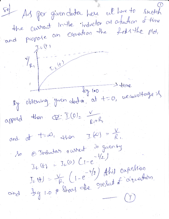
1. An RL circuit comprised of one resistor and one inductor is shown in the figure below. The resistor and inductor...
 1. An RL circuit comprised of one resistor and one inductor is shown in the figure below. The resistor and inductor are connected to a source of emf with negligible internal resistance by a switch a. The emf for this circuit is 12.0 V. The resistance of the resistor is 0.35 , and the inductance of the inductor is 53 mH. For the circuit below: a. Sketch the graph of current through the inductor as a function of time after...
The figure shows a segment of a circuit with a resistor and an inductor. The current...
 The figure shows a segment of a circuit with a resistor and an
inductor. The current (in the direction shown) changes in time as
shown in the graph of current as a function of time.
Rank (delta) Vba at the five times shown from most positive to
most negative.
Rank (delta) Vdc at the five times shown from most positive to
most negative.
The figure shows a segment of a circuit with a resistor and an inductor. The current (in...
The figure shows a segment of a circuit with a resistor and an
inductor. The current (in the direction shown) changes in time as
shown in the graph of current as a function of time.
Rank (delta) Vba at the five times shown from most positive to
most negative.
Rank (delta) Vdc at the five times shown from most positive to
most negative.
The figure shows a segment of a circuit with a resistor and an inductor. The current (in...
1. An RL circuit comprised of one resistor and one inductor is shown in the figure...
 1. An RL circuit comprised of one resistor and one inductor is shown in the figure below. The resistor and inductor are connected to a source of emf with negligible internal resistance by a switch a. The emf for this circuit is 12.0 V. The resistance of the resistor is 0.35 12, and the inductance of the inductor is 53 mH. For the circuit below: a. Sketch the graph of current through the inductor as a function of time after...
Help please ...! An RL circuit comprised of one resistor and one inductor is shown in...
 Help please ...!
An RL circuit comprised of one resistor and one inductor is shown in the figure below. The resistor and inductor are connected to a source of emf with negligible internal resistance by a switch a. The emf for this circuit is 12.0 V. The resistance of the resistor is 0.35 Q, and the inductance of the inductor is 53 mH. For the circuit below: Sketch the graph of current through the inductor as a function of time...
Help please ...!
An RL circuit comprised of one resistor and one inductor is shown in the figure below. The resistor and inductor are connected to a source of emf with negligible internal resistance by a switch a. The emf for this circuit is 12.0 V. The resistance of the resistor is 0.35 Q, and the inductance of the inductor is 53 mH. For the circuit below: Sketch the graph of current through the inductor as a function of time...
A circuit is constructed with four resistors, one inductor, one battery and a switch as shown....
 A circuit is constructed with four resistors, one inductor, one battery and a switch as shown. The values for the resistors are: R1-R2-76 Ω, R3-105 Ω and R4-810. The inductance is L-478 mH and the battery voltage is V-24 V 1) The switch has been open for a long time when at time t - o, the switch is closed. What is 11(0), the magnitude of the current through the resistor R1 just after the switch is closed? A uIii...
5. (4) Consider an RL circuit that can initially be thought of as containing an ideal...
5. (4) Consider an RL circuit that can initially be thought of as containing an ideal battery of voltage 2.10 V, an ideal resistor of resistance 910 Ω and an ideal inductor of inductance 77.50 mH. (a) Another ideal inductor, of inductance 125.0 mH, is added in series. Find the new equivalent inductance and the new time constant for the circuit. (b) The circuit is closed at t=0. Sketch the behaviour of the voltage across the resistor and the voltage...
Please help, I'm struggling. Thank you An RL circuit comprised of one resistor and one inductor...
 Please help, I'm struggling. Thank you
An RL circuit comprised of one resistor and one inductor is shown in the figure below. The resistor and inductor are connected to a source of emf with negligible internal resistance by a switch a. The emf for this circuit is 12.0V. The resistance of the resistor is 0.35 12, and the inductance of the inductor is 53 mH. For the circuit below: a. Sketch the graph of current through the inductor as a...
Please help, I'm struggling. Thank you
An RL circuit comprised of one resistor and one inductor is shown in the figure below. The resistor and inductor are connected to a source of emf with negligible internal resistance by a switch a. The emf for this circuit is 12.0V. The resistance of the resistor is 0.35 12, and the inductance of the inductor is 53 mH. For the circuit below: a. Sketch the graph of current through the inductor as a...
 In a circuit, a parallel combination of a resistor
R2 = 20.3 Ω and an inductor of L =
3.70 mH is connected in series with a resistor of
R1 = 5.80 Ω, a 6.00-V dc battery, and a
switch.
What is the voltage across the 5.80-Ω resistor immediately after
the switch is closed?
What is the current in the 3.70-mH inductor after the switch has
been closed for a long time?
6.00 V I SR,
In a circuit, a parallel combination of a resistor
R2 = 20.3 Ω and an inductor of L =
3.70 mH is connected in series with a resistor of
R1 = 5.80 Ω, a 6.00-V dc battery, and a
switch.
What is the voltage across the 5.80-Ω resistor immediately after
the switch is closed?
What is the current in the 3.70-mH inductor after the switch has
been closed for a long time?
6.00 V I SR,
 Pre-lab EM-5 Ohm's Law and Kirchhoff's Rules Ohm's Law The resistance R of a device can be determined by either directly measuring the resistance using an ohmmeter, or by measuring the current I through it and the voltage Vacross it, and then calculating R using Ohm's Law V R= (1) If the voltage across a resistor is 10V, and the current passing through it is 2.5 mA. of the resistor? What is the resistance R= Ω. Kirchhoffs Loop Rule Around...
 1. An RL circuit comprised of one resistor and one inductor is shown in the figure below. The resistor and inductor are connected to a source of emf with negligible internal resistance by a switch a. The emf for this circuit is 12.0 V. The resistance of the resistor is 0.35 , and the inductance of the inductor is 53 mH. For the circuit below: a. Sketch the graph of current through the inductor as a function of time after...
 The figure shows a segment of a circuit with a resistor and an
inductor. The current (in the direction shown) changes in time as
shown in the graph of current as a function of time.
Rank (delta) Vba at the five times shown from most positive to
most negative.
Rank (delta) Vdc at the five times shown from most positive to
most negative.
The figure shows a segment of a circuit with a resistor and an inductor. The current (in...
The figure shows a segment of a circuit with a resistor and an
inductor. The current (in the direction shown) changes in time as
shown in the graph of current as a function of time.
Rank (delta) Vba at the five times shown from most positive to
most negative.
Rank (delta) Vdc at the five times shown from most positive to
most negative.
The figure shows a segment of a circuit with a resistor and an inductor. The current (in...
 1. An RL circuit comprised of one resistor and one inductor is shown in the figure below. The resistor and inductor are connected to a source of emf with negligible internal resistance by a switch a. The emf for this circuit is 12.0 V. The resistance of the resistor is 0.35 12, and the inductance of the inductor is 53 mH. For the circuit below: a. Sketch the graph of current through the inductor as a function of time after...
 1. An RL circuit comprised of one resistor and one inductor is shown in the figure below. The resistor and inductor are connected to a source of emf with negligible internal resistance by a switch a. The emf for this circuit is 12.0 V. The resistance of the resistor is 0.35 12, and the inductance of the inductor is 53 mH. For the circuit below: a. Sketch the graph of current through the inductor as a function of time after...
 Help please ...!
An RL circuit comprised of one resistor and one inductor is shown in the figure below. The resistor and inductor are connected to a source of emf with negligible internal resistance by a switch a. The emf for this circuit is 12.0 V. The resistance of the resistor is 0.35 Q, and the inductance of the inductor is 53 mH. For the circuit below: Sketch the graph of current through the inductor as a function of time...
Help please ...!
An RL circuit comprised of one resistor and one inductor is shown in the figure below. The resistor and inductor are connected to a source of emf with negligible internal resistance by a switch a. The emf for this circuit is 12.0 V. The resistance of the resistor is 0.35 Q, and the inductance of the inductor is 53 mH. For the circuit below: Sketch the graph of current through the inductor as a function of time...
 A circuit is constructed with four resistors, one inductor, one battery and a switch as shown. The values for the resistors are: R1-R2-76 Ω, R3-105 Ω and R4-810. The inductance is L-478 mH and the battery voltage is V-24 V 1) The switch has been open for a long time when at time t - o, the switch is closed. What is 11(0), the magnitude of the current through the resistor R1 just after the switch is closed? A uIii...
 Please help, I'm struggling. Thank you
An RL circuit comprised of one resistor and one inductor is shown in the figure below. The resistor and inductor are connected to a source of emf with negligible internal resistance by a switch a. The emf for this circuit is 12.0V. The resistance of the resistor is 0.35 12, and the inductance of the inductor is 53 mH. For the circuit below: a. Sketch the graph of current through the inductor as a...
Please help, I'm struggling. Thank you
An RL circuit comprised of one resistor and one inductor is shown in the figure below. The resistor and inductor are connected to a source of emf with negligible internal resistance by a switch a. The emf for this circuit is 12.0V. The resistance of the resistor is 0.35 12, and the inductance of the inductor is 53 mH. For the circuit below: a. Sketch the graph of current through the inductor as a...
Most questions answered within 3 hours.
-
Given P(Ec ) = 0.43, P(F) = 0.52, and P(EF) = 0.18.
Find P( E |...
asked 38 minutes ago -
Consider two empty containers A and B whose volumes are
10mL and 20mL respectively. 1mL of...
asked 41 minutes ago -
QUESTION 6
Determine the linear momentum of a 2,800 kg houseboat going 3
m/s.
9,100 kg.m/s...
asked 56 minutes ago -
Jor-el throws a ball upward from the top of a 728 foot building
on the planet...
asked 1 hour ago -
Which of the following will most likely to happen if Federal
Reserve Bank decreases the money...
asked 42 minutes ago -
You’ve just joined the investment banking firm of Dewey,
Cheatum, and Howe. They’ve offered you two...
asked 36 minutes ago -
An air conditioner cools 226 m^3/min of humid air at 36 oC and
98% relative humidity...
asked 36 minutes ago -
Vaughn Manufacturing acquires a coal mine at a cost of $1870000.
Intangible development costs total $354000....
asked 45 minutes ago -
Question 5
What effect would a decrease in
temperature have on pressure, assuming that volume
(T)...
asked 57 minutes ago -
Draw the Lewis dot structures for the following molecules. None
of the atoms have a formal...
asked 1 hour ago -
What does it mean when an element is radioactive?
a.
It means the element is changing...
asked 1 hour ago -
A company deposits $6,000 in a bank at the end of every year for
10 years....
asked 1 hour ago