
Homework Answers

Add Answer to:
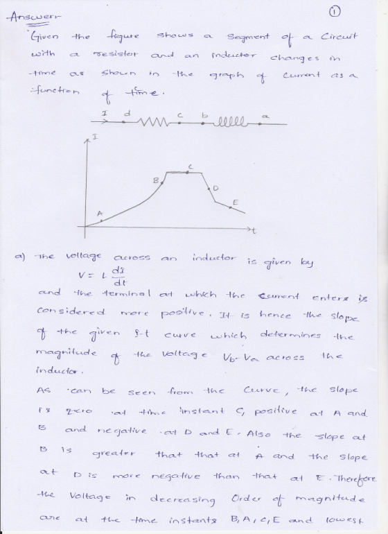
The figure shows a segment of a circuit with a resistor and an
inductor. The current...
1. An RL circuit comprised of one resistor and one inductor is shown in the figure below. The resistor and inductor...
 1. An RL circuit comprised of one resistor and one inductor is shown in the figure below. The resistor and inductor are connected to a source of emf with negligible internal resistance by a switch a. The emf for this circuit is 12.0 V. The resistance of the resistor is 0.35 , and the inductance of the inductor is 53 mH. For the circuit below: a. Sketch the graph of current through the inductor as a function of time after...
1. An RL circuit comprised of one resistor and one inductor is shown in the figure...
 1. An RL circuit comprised of one resistor and one inductor is shown in the figure below. The resistor and inductor are connected to a source of emf with negligible internal resistance by a switch a. The emf for this circuit is 12.0 V. The resistance of the resistor is 0.35 12, and the inductance of the inductor is 53 mH. For the circuit below: a. Sketch the graph of current through the inductor as a function of time after...
An (open) electrical circuit consists of an inductor, a resistor, and a capacitor. There is an...
 An (open) electrical circuit consists of an inductor, a resistor, and a capacitor. There is an initial charge of 1 coulomb on the capacitor. At the instant the circuit is closed, a current of 5 amperes is present and a voltage of E(t) = 23 cost is applied. In this circuit the voltage drop across the resistor is 5 times the instantaneous change in the charge, the voltage drop across capacitor is 11 times the charge, and the voltage drop...
1) An (open) electrical circuit consists of an inductor, a resistor, and a capacitor. There is...
1) An (open) electrical circuit consists of an inductor, a resistor, and a capacitor. There is an initial charge of 1 coulomb on the capacitor. At the instant the circuit is closed, a current of 7 amperes is present and a voltage of E(t) = 20 cos t is applied. In this circuit the voltage drop across the resistor is 7 times the instantaneous change in the charge, the voltage drop across the capacitor is 11 times the charge, and...
Decay of Current in an L-R Circuit
 Learning Goal: To understand the mathematics of current decay in an L-R circuitA DC voltage source is connected to a resistor of resistance R and an inductor with inductance L, forming the circuit shown in the figure. For a long time before t=0, the switch has been in the position shown, so that a current I0 has been built up in the circuit by the voltage source. At t=0 the switch is thrown to remove the voltage source from the circuit. This...
In the circuit in the figure, determine the current in each resistor and the voltage across...
 In the circuit in the figure, determine the
current in each resistor and the voltage across the 70
? resistor. (Indicate the
direction of the current flow through each resistor through the
sign of your answer. Take upward current flow as positive.)
current in 200 ?
current in 80 ?
current in 20 ?
current in 70 ?
voltage across 70 ? resistor:
In the circuit in the figure, determine the
current in each resistor and the voltage across the 70
? resistor. (Indicate the
direction of the current flow through each resistor through the
sign of your answer. Take upward current flow as positive.)
current in 200 ?
current in 80 ?
current in 20 ?
current in 70 ?
voltage across 70 ? resistor:
Help please ...! An RL circuit comprised of one resistor and one inductor is shown in...
 Help please ...!
An RL circuit comprised of one resistor and one inductor is shown in the figure below. The resistor and inductor are connected to a source of emf with negligible internal resistance by a switch a. The emf for this circuit is 12.0 V. The resistance of the resistor is 0.35 Q, and the inductance of the inductor is 53 mH. For the circuit below: Sketch the graph of current through the inductor as a function of time...
Help please ...!
An RL circuit comprised of one resistor and one inductor is shown in the figure below. The resistor and inductor are connected to a source of emf with negligible internal resistance by a switch a. The emf for this circuit is 12.0 V. The resistance of the resistor is 0.35 Q, and the inductance of the inductor is 53 mH. For the circuit below: Sketch the graph of current through the inductor as a function of time...
A circuit is constructed with an AC generator, a resistor, capacitor and inductor as shown. The...
 A circuit is constructed with an AC generator,
a resistor, capacitor and inductor as shown. The generator voltage
varies in time as ? =Va - Vb =
?msin?t, where
?m = 120 V and ? =
221 radians/second. The inductance L = 352 mH. The values for the
capacitance C and the resistance R are unkown. What is known is
that the current in the circuit leads the voltage across the
generator by ? = 58 degrees and the average...
A circuit is constructed with an AC generator,
a resistor, capacitor and inductor as shown. The generator voltage
varies in time as ? =Va - Vb =
?msin?t, where
?m = 120 V and ? =
221 radians/second. The inductance L = 352 mH. The values for the
capacitance C and the resistance R are unkown. What is known is
that the current in the circuit leads the voltage across the
generator by ? = 58 degrees and the average...
Please help, I'm struggling. Thank you An RL circuit comprised of one resistor and one inductor...
 Please help, I'm struggling. Thank you
An RL circuit comprised of one resistor and one inductor is shown in the figure below. The resistor and inductor are connected to a source of emf with negligible internal resistance by a switch a. The emf for this circuit is 12.0V. The resistance of the resistor is 0.35 12, and the inductance of the inductor is 53 mH. For the circuit below: a. Sketch the graph of current through the inductor as a...
Please help, I'm struggling. Thank you
An RL circuit comprised of one resistor and one inductor is shown in the figure below. The resistor and inductor are connected to a source of emf with negligible internal resistance by a switch a. The emf for this circuit is 12.0V. The resistance of the resistor is 0.35 12, and the inductance of the inductor is 53 mH. For the circuit below: a. Sketch the graph of current through the inductor as a...
 1. An RL circuit comprised of one resistor and one inductor is shown in the figure below. The resistor and inductor are connected to a source of emf with negligible internal resistance by a switch a. The emf for this circuit is 12.0 V. The resistance of the resistor is 0.35 , and the inductance of the inductor is 53 mH. For the circuit below: a. Sketch the graph of current through the inductor as a function of time after...
 1. An RL circuit comprised of one resistor and one inductor is shown in the figure below. The resistor and inductor are connected to a source of emf with negligible internal resistance by a switch a. The emf for this circuit is 12.0 V. The resistance of the resistor is 0.35 12, and the inductance of the inductor is 53 mH. For the circuit below: a. Sketch the graph of current through the inductor as a function of time after...
 1. An RL circuit comprised of one resistor and one inductor is shown in the figure below. The resistor and inductor are connected to a source of emf with negligible internal resistance by a switch a. The emf for this circuit is 12.0 V. The resistance of the resistor is 0.35 12, and the inductance of the inductor is 53 mH. For the circuit below: a. Sketch the graph of current through the inductor as a function of time after...
 An (open) electrical circuit consists of an inductor, a resistor, and a capacitor. There is an initial charge of 1 coulomb on the capacitor. At the instant the circuit is closed, a current of 5 amperes is present and a voltage of E(t) = 23 cost is applied. In this circuit the voltage drop across the resistor is 5 times the instantaneous change in the charge, the voltage drop across capacitor is 11 times the charge, and the voltage drop...
 In the circuit in the figure, determine the
current in each resistor and the voltage across the 70
? resistor. (Indicate the
direction of the current flow through each resistor through the
sign of your answer. Take upward current flow as positive.)
current in 200 ?
current in 80 ?
current in 20 ?
current in 70 ?
voltage across 70 ? resistor:
In the circuit in the figure, determine the
current in each resistor and the voltage across the 70
? resistor. (Indicate the
direction of the current flow through each resistor through the
sign of your answer. Take upward current flow as positive.)
current in 200 ?
current in 80 ?
current in 20 ?
current in 70 ?
voltage across 70 ? resistor:
 Help please ...!
An RL circuit comprised of one resistor and one inductor is shown in the figure below. The resistor and inductor are connected to a source of emf with negligible internal resistance by a switch a. The emf for this circuit is 12.0 V. The resistance of the resistor is 0.35 Q, and the inductance of the inductor is 53 mH. For the circuit below: Sketch the graph of current through the inductor as a function of time...
Help please ...!
An RL circuit comprised of one resistor and one inductor is shown in the figure below. The resistor and inductor are connected to a source of emf with negligible internal resistance by a switch a. The emf for this circuit is 12.0 V. The resistance of the resistor is 0.35 Q, and the inductance of the inductor is 53 mH. For the circuit below: Sketch the graph of current through the inductor as a function of time...
 A circuit is constructed with an AC generator,
a resistor, capacitor and inductor as shown. The generator voltage
varies in time as ? =Va - Vb =
?msin?t, where
?m = 120 V and ? =
221 radians/second. The inductance L = 352 mH. The values for the
capacitance C and the resistance R are unkown. What is known is
that the current in the circuit leads the voltage across the
generator by ? = 58 degrees and the average...
A circuit is constructed with an AC generator,
a resistor, capacitor and inductor as shown. The generator voltage
varies in time as ? =Va - Vb =
?msin?t, where
?m = 120 V and ? =
221 radians/second. The inductance L = 352 mH. The values for the
capacitance C and the resistance R are unkown. What is known is
that the current in the circuit leads the voltage across the
generator by ? = 58 degrees and the average...
 Please help, I'm struggling. Thank you
An RL circuit comprised of one resistor and one inductor is shown in the figure below. The resistor and inductor are connected to a source of emf with negligible internal resistance by a switch a. The emf for this circuit is 12.0V. The resistance of the resistor is 0.35 12, and the inductance of the inductor is 53 mH. For the circuit below: a. Sketch the graph of current through the inductor as a...
Please help, I'm struggling. Thank you
An RL circuit comprised of one resistor and one inductor is shown in the figure below. The resistor and inductor are connected to a source of emf with negligible internal resistance by a switch a. The emf for this circuit is 12.0V. The resistance of the resistor is 0.35 12, and the inductance of the inductor is 53 mH. For the circuit below: a. Sketch the graph of current through the inductor as a...
Most questions answered within 3 hours.
-
(Expected rate of return and risk) Carter Inc. is evaluating a
security. Calculate the investment’s expected...
asked 26 minutes ago -
What specific indicators can point to lack of progress for
African Americans in American society?
asked 1 hour ago -
1-The Electrons in a beam are moving at 2.7×10⁸ m/s in an
electric field of 15000...
asked 1 hour ago -
A gas tank is a vertical cylinder. It has a radius of 1m, a
height of...
asked 2 hours ago -
Accent Software faces the following conditions. All of these
support Accent’s use of a market-penetration pricing...
asked 3 hours ago -
A mathematically inclined friend emails you the following
instructions: "Meet me in the cafeteria the first...
asked 3 hours ago -
A monopoly sells in two countries . The demand curves in the two
countries are p1...
asked 4 hours ago -
A .15kg rubber ball is bounced off a wall. Before hitting the
wall, the ball moves...
asked 4 hours ago -
A manufacturing company preparing to build a new plant is
considering three potential locations for it....
asked 4 hours ago -
B. If compound Y has approximately the same values of solubility
in toluene as compound X,...
asked 5 hours ago -
Oscar Inc. has inventory in Japan valued at 39,051,000 Yen one
year ago. One year ago...
asked 5 hours ago -
If Canada suffered from "fundamental disequilibrium," and its
government choose not to devalue its currency, a...
asked 5 hours ago