
Please answer question 3 parts a,b,c thank you
Reinforced Concrete HW
Homework Answers

Add Answer to:
Please answer question 3 parts a,b,c thank you
Reinforced Concrete HW
3. (40 pts) Analyze the...
Please answer question 4 thank you. Results from problem 3 are shown above Reinforced Concrete 3....
 Please answer question 4 thank you. Results from problem 3 are
shown above
Reinforced Concrete
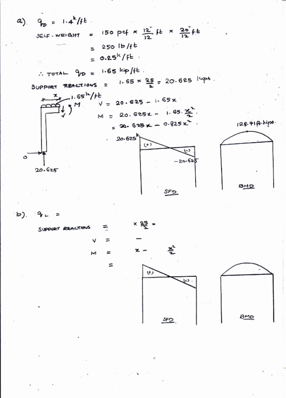
3. (40 pts) Analyze the following statically determinate frame by hand and clearly draw the shear force, axial force, and bending moment diagrams indicating relevant (maximum and minimum) values for each of the following load cases: a) Uniform dead load (qo) applied on the beam – must add beam self-weight (concrete) to this value. b) Uniform live load (q) applied on the beam. c) Horizontal...
Please answer question 4 thank you. Results from problem 3 are
shown above
Reinforced Concrete
3. (40 pts) Analyze the following statically determinate frame by hand and clearly draw the shear force, axial force, and bending moment diagrams indicating relevant (maximum and minimum) values for each of the following load cases: a) Uniform dead load (qo) applied on the beam – must add beam self-weight (concrete) to this value. b) Uniform live load (q) applied on the beam. c) Horizontal...
3. (40 pts) Analyze the following statically determinate frame by hand and clearly draw the shear...
 3. (40 pts) Analyze the following statically determinate frame by hand and clearly draw the shear force, axial force, and bending moment diagrams indicating relevant (maximum and minimum) values for each of the following load cases: a) Uniform dead load (q) applied on the beam must add beam self-weight (concrete) to this value b) Uniform live load (qu) applied on the beam. c) Horizontal wind force (H H=12kip 12 x 20 gp-1.4 kip/ft -2.0 kip/ft 14 ft 12" x 12...
Please answer question 1 thank you Reinforced Concrete HW 18%20(2).pdf CEE433- Homework Assignment 9 Assigned: 12...
 Please answer question 1 thank you
Reinforced Concrete HW
18%20(2).pdf CEE433- Homework Assignment 9 Assigned: 12 April 2018 Due: 19 April 2018 1. Design the shear reinforcement (vertical stirrups) for the beam shown in the figure. Design stirrups based on the shear envelope using the approximate procedure discussed in class. Note that for the overhangs the maximum shear at the support is induced by placing dead and live loads throughout the cantilever portion. Satisfy all strength and spacing requirements specified...
Please answer question 1 thank you
Reinforced Concrete HW
18%20(2).pdf CEE433- Homework Assignment 9 Assigned: 12 April 2018 Due: 19 April 2018 1. Design the shear reinforcement (vertical stirrups) for the beam shown in the figure. Design stirrups based on the shear envelope using the approximate procedure discussed in class. Note that for the overhangs the maximum shear at the support is induced by placing dead and live loads throughout the cantilever portion. Satisfy all strength and spacing requirements specified...
please solve completely and correctly, I will give thumbs up! Force Method. The reinforced concrete beam as sh...
 please solve completely and correctly, I will give thumbs
up!
Force Method. The reinforced concrete beam as shown in “Figure 1" has a constant cross sectional dimension of 10" x 12" (b x h). The unit weight of the concrete is 150 lb/ft3. The 28-day concrete compressive strength of the beam is = 4000 psi. Use the classical force method to analyze the indeterminate beam under the applied dead load only. Assume the following values of span length: L1 =...
please solve completely and correctly, I will give thumbs
up!
Force Method. The reinforced concrete beam as shown in “Figure 1" has a constant cross sectional dimension of 10" x 12" (b x h). The unit weight of the concrete is 150 lb/ft3. The 28-day concrete compressive strength of the beam is = 4000 psi. Use the classical force method to analyze the indeterminate beam under the applied dead load only. Assume the following values of span length: L1 =...
Problem 1 Reinforced Concrete T-Flanged Sections (50 pts.) You are required to analyze and design...
 Problem 1 Reinforced Concrete T-Flanged Sections (50 pts.) You are required to analyze and design the propped cantilever t-section from HM 4 but for shear only. Draw shear V and moment M diagrams for uniformly distributed load throughout the 30ft span and equally concentrated loads at 10ft and 30ft. Recall that the connection at the left joint N1 is fixed. The connection at 20ft N3 is a roller. The right end node N2 is a free end. Usea concrete compressive...
Problem 1 Reinforced Concrete T-Flanged Sections (50 pts.) You are required to analyze and design...
 Problem 1 Reinforced Concrete T-Flanged Sections (50 pts.) You are required to analyze and design the propped cantilever t-section from HM 4 but for shear only. Draw shear V and moment M diagrams for uniformly distributed load throughout the 30ft span and equally concentrated loads at 10ft and 30ft. Recall that the connection at the left joint N1 is fixed. The connection at 20ft N3 is a roller. The right end node N2 is a free end. Use a concrete...
Please answer question 3. The dimensions are given in problem 1 thank you Reinforced Concrete df...
 Please answer question 3. The dimensions are given in problem 1
thank you
Reinforced Concrete
df Assigned: 20 February 2018 Due: 01 March 2018 1. For the rectangular cross section shown compute the nominal (M,) and design flexural strength (OM.) using the different reinforcement ratios corresponding to a net tensile strain of 0.002, 0.0025, 0.0030, 0.0035, 0.004, 0.0045, 0.005. Use f, = 60,000 psi and f', = 4,000 psi. Using these data points, plot M, and OM, as a function...
Please answer question 3. The dimensions are given in problem 1
thank you
Reinforced Concrete
df Assigned: 20 February 2018 Due: 01 March 2018 1. For the rectangular cross section shown compute the nominal (M,) and design flexural strength (OM.) using the different reinforcement ratios corresponding to a net tensile strain of 0.002, 0.0025, 0.0030, 0.0035, 0.004, 0.0045, 0.005. Use f, = 60,000 psi and f', = 4,000 psi. Using these data points, plot M, and OM, as a function...
structures homework, please answer all parts of the question thank you 2. Wood Beam Design Design...
 structures homework, please answer all parts of the question thank
you
2. Wood Beam Design Design a 2x dimensioned lumber floor joist to carry the given dead + live floor load (neglect joist selfweight). Assume the floor meets conditions of 4.4.1 so CL=1.0. Also Ct, Cfu, and Ci = 1.0. Find the short term deflection of your chosen beam under live load only (100% LL is short term). Compare your LL deflection with the code limit of L/360. SPAN DATASET:...
structures homework, please answer all parts of the question thank
you
2. Wood Beam Design Design a 2x dimensioned lumber floor joist to carry the given dead + live floor load (neglect joist selfweight). Assume the floor meets conditions of 4.4.1 so CL=1.0. Also Ct, Cfu, and Ci = 1.0. Find the short term deflection of your chosen beam under live load only (100% LL is short term). Compare your LL deflection with the code limit of L/360. SPAN DATASET:...
PLESAE CONTINUE FROM C,D IF you consider the whole question to be too long thanks here...
 PLESAE
CONTINUE FROM C,D IF you consider the whole question to be too long
thanks
here are some support information
The below wooden double overhanging beam is under a uniformly distributed load w. The wood is weak along the orientation of the grain (or wood cell fibres) that makes an angle of 30° with the horizontal (see figure). The maximum shear stress on a plane parallel to the grain that the wood can sustain is tmax = 5 MPa, and...
PLESAE
CONTINUE FROM C,D IF you consider the whole question to be too long
thanks
here are some support information
The below wooden double overhanging beam is under a uniformly distributed load w. The wood is weak along the orientation of the grain (or wood cell fibres) that makes an angle of 30° with the horizontal (see figure). The maximum shear stress on a plane parallel to the grain that the wood can sustain is tmax = 5 MPa, and...
 Please answer question 4 thank you. Results from problem 3 are
shown above
Reinforced Concrete
3. (40 pts) Analyze the following statically determinate frame by hand and clearly draw the shear force, axial force, and bending moment diagrams indicating relevant (maximum and minimum) values for each of the following load cases: a) Uniform dead load (qo) applied on the beam – must add beam self-weight (concrete) to this value. b) Uniform live load (q) applied on the beam. c) Horizontal...
Please answer question 4 thank you. Results from problem 3 are
shown above
Reinforced Concrete
3. (40 pts) Analyze the following statically determinate frame by hand and clearly draw the shear force, axial force, and bending moment diagrams indicating relevant (maximum and minimum) values for each of the following load cases: a) Uniform dead load (qo) applied on the beam – must add beam self-weight (concrete) to this value. b) Uniform live load (q) applied on the beam. c) Horizontal...
 3. (40 pts) Analyze the following statically determinate frame by hand and clearly draw the shear force, axial force, and bending moment diagrams indicating relevant (maximum and minimum) values for each of the following load cases: a) Uniform dead load (q) applied on the beam must add beam self-weight (concrete) to this value b) Uniform live load (qu) applied on the beam. c) Horizontal wind force (H H=12kip 12 x 20 gp-1.4 kip/ft -2.0 kip/ft 14 ft 12" x 12...
 Please answer question 1 thank you
Reinforced Concrete HW
18%20(2).pdf CEE433- Homework Assignment 9 Assigned: 12 April 2018 Due: 19 April 2018 1. Design the shear reinforcement (vertical stirrups) for the beam shown in the figure. Design stirrups based on the shear envelope using the approximate procedure discussed in class. Note that for the overhangs the maximum shear at the support is induced by placing dead and live loads throughout the cantilever portion. Satisfy all strength and spacing requirements specified...
Please answer question 1 thank you
Reinforced Concrete HW
18%20(2).pdf CEE433- Homework Assignment 9 Assigned: 12 April 2018 Due: 19 April 2018 1. Design the shear reinforcement (vertical stirrups) for the beam shown in the figure. Design stirrups based on the shear envelope using the approximate procedure discussed in class. Note that for the overhangs the maximum shear at the support is induced by placing dead and live loads throughout the cantilever portion. Satisfy all strength and spacing requirements specified...
 please solve completely and correctly, I will give thumbs
up!
Force Method. The reinforced concrete beam as shown in “Figure 1" has a constant cross sectional dimension of 10" x 12" (b x h). The unit weight of the concrete is 150 lb/ft3. The 28-day concrete compressive strength of the beam is = 4000 psi. Use the classical force method to analyze the indeterminate beam under the applied dead load only. Assume the following values of span length: L1 =...
please solve completely and correctly, I will give thumbs
up!
Force Method. The reinforced concrete beam as shown in “Figure 1" has a constant cross sectional dimension of 10" x 12" (b x h). The unit weight of the concrete is 150 lb/ft3. The 28-day concrete compressive strength of the beam is = 4000 psi. Use the classical force method to analyze the indeterminate beam under the applied dead load only. Assume the following values of span length: L1 =...
 Problem 1 Reinforced Concrete T-Flanged Sections (50 pts.) You are required to analyze and design the propped cantilever t-section from HM 4 but for shear only. Draw shear V and moment M diagrams for uniformly distributed load throughout the 30ft span and equally concentrated loads at 10ft and 30ft. Recall that the connection at the left joint N1 is fixed. The connection at 20ft N3 is a roller. The right end node N2 is a free end. Usea concrete compressive...
 Problem 1 Reinforced Concrete T-Flanged Sections (50 pts.) You are required to analyze and design the propped cantilever t-section from HM 4 but for shear only. Draw shear V and moment M diagrams for uniformly distributed load throughout the 30ft span and equally concentrated loads at 10ft and 30ft. Recall that the connection at the left joint N1 is fixed. The connection at 20ft N3 is a roller. The right end node N2 is a free end. Use a concrete...
 Please answer question 3. The dimensions are given in problem 1
thank you
Reinforced Concrete
df Assigned: 20 February 2018 Due: 01 March 2018 1. For the rectangular cross section shown compute the nominal (M,) and design flexural strength (OM.) using the different reinforcement ratios corresponding to a net tensile strain of 0.002, 0.0025, 0.0030, 0.0035, 0.004, 0.0045, 0.005. Use f, = 60,000 psi and f', = 4,000 psi. Using these data points, plot M, and OM, as a function...
Please answer question 3. The dimensions are given in problem 1
thank you
Reinforced Concrete
df Assigned: 20 February 2018 Due: 01 March 2018 1. For the rectangular cross section shown compute the nominal (M,) and design flexural strength (OM.) using the different reinforcement ratios corresponding to a net tensile strain of 0.002, 0.0025, 0.0030, 0.0035, 0.004, 0.0045, 0.005. Use f, = 60,000 psi and f', = 4,000 psi. Using these data points, plot M, and OM, as a function...
 structures homework, please answer all parts of the question thank
you
2. Wood Beam Design Design a 2x dimensioned lumber floor joist to carry the given dead + live floor load (neglect joist selfweight). Assume the floor meets conditions of 4.4.1 so CL=1.0. Also Ct, Cfu, and Ci = 1.0. Find the short term deflection of your chosen beam under live load only (100% LL is short term). Compare your LL deflection with the code limit of L/360. SPAN DATASET:...
structures homework, please answer all parts of the question thank
you
2. Wood Beam Design Design a 2x dimensioned lumber floor joist to carry the given dead + live floor load (neglect joist selfweight). Assume the floor meets conditions of 4.4.1 so CL=1.0. Also Ct, Cfu, and Ci = 1.0. Find the short term deflection of your chosen beam under live load only (100% LL is short term). Compare your LL deflection with the code limit of L/360. SPAN DATASET:...
 PLESAE
CONTINUE FROM C,D IF you consider the whole question to be too long
thanks
here are some support information
The below wooden double overhanging beam is under a uniformly distributed load w. The wood is weak along the orientation of the grain (or wood cell fibres) that makes an angle of 30° with the horizontal (see figure). The maximum shear stress on a plane parallel to the grain that the wood can sustain is tmax = 5 MPa, and...
PLESAE
CONTINUE FROM C,D IF you consider the whole question to be too long
thanks
here are some support information
The below wooden double overhanging beam is under a uniformly distributed load w. The wood is weak along the orientation of the grain (or wood cell fibres) that makes an angle of 30° with the horizontal (see figure). The maximum shear stress on a plane parallel to the grain that the wood can sustain is tmax = 5 MPa, and...
Most questions answered within 3 hours.
-
The factory method and the abstract factory pattern use
different object oriented
mechanisms are used to...
asked 2 hours ago -
Given the data below for the monthly sales data at each branch in
your region for...
asked 3 hours ago -
Blossom Company owns 10000 of the 50000 outstanding shares of
Taylor, Inc. common stock. During 2018,...
asked 4 hours ago -
Calculate the following: ***SHOW ALL WORK!!!! Or
NO CREDIT*** Circle your answers. 8pts
each
In the...
asked 6 hours ago -
Bank Z is currently advertising interest rates on its checking
account. They claim to pay an...
asked 5 hours ago -
List two ways of transformation on the response variable that
can be used to deal with...
asked 6 hours ago -
If a 2000 ohm resistor has a -3.90 mA current going through it.
What is the...
asked 6 hours ago -
Please comment on the sentences.
Some types of jobs require more training than others. Some
companies...
asked 7 hours ago -
The )G01 for the hydrolysis of phosphorarginine
reaction depicted below is –32 kJ mol-1.
Phosphoarginine ...
asked 8 hours ago -
Cross a heterozygous blue-eyed goat with a homozygous brown-eyed
goat. Be sure to indicate which kids...
asked 8 hours ago -
Use the following information to answer the next two
questions.
Please refer to question 9-90. A...
asked 9 hours ago -
A solution containing 0.050 g of an unknown electrolyte in 2.50
g of cyclohexane was found...
asked 9 hours ago