
Homework Answers
Add Answer to:
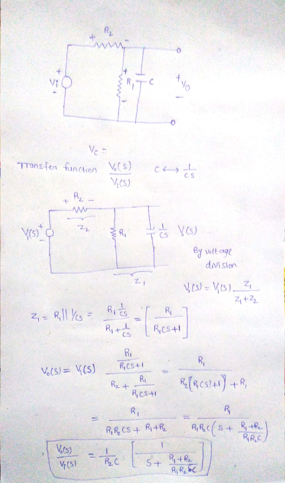
Calculate the transfer function T(s) = in the circuit shown using the impedance concept. Write the...
Question 1 For the circuit shown in figure 1; i. Find the transfer impedance function, H(s)...
 Question 1 For the circuit shown in figure 1; i. Find the transfer impedance function, H(s) = Vds(s) Find the poles and zeros for this transfer function and plot them on the s - Find the magnitude of the transfer function in decibels. [10] s-plane [8] ii [3] 2H 20 20 2 H Figure Question 2 The hybrid parameters (h-parameters) for the two -port network circuit in figure 2 are; 5 h=2 0.05 Find the equivalent impedance parameters (z-parameters) Find...
Problem 4 (20 %) For the circuit shown in Figure 4 determine IB, IC, and VC....
 Problem 4 (20 %) For the circuit shown in Figure 4 determine IB,
IC, and VC. Data VCC=9 V VBB=4 V R2= 165 k R1= 2.5 k Transistor
Assume VBE ≈ 0.7 V and =150
Derive all the results. Give the answers with the preestablished
prefix.
FAVOR DIBUJAR LOS CIRCUITOS
Problem 4 (206) For the circuit shown in Figure 4 determine IB, I, and Vc. Data Ve=9 V V=4V R = 165 kg R=2.5k_2 Transistor Assume VE 0.7 V and...
Problem 4 (20 %) For the circuit shown in Figure 4 determine IB,
IC, and VC. Data VCC=9 V VBB=4 V R2= 165 k R1= 2.5 k Transistor
Assume VBE ≈ 0.7 V and =150
Derive all the results. Give the answers with the preestablished
prefix.
FAVOR DIBUJAR LOS CIRCUITOS
Problem 4 (206) For the circuit shown in Figure 4 determine IB, I, and Vc. Data Ve=9 V V=4V R = 165 kg R=2.5k_2 Transistor Assume VE 0.7 V and...
1. Consider the circuit shown below. Cl e, (0) c, e。(t) Find the transfer function below using t...
 Please help with this dynamics circuit
analysis.
Please show work and explain.
Thank you!!
1. Consider the circuit shown below. Cl e, (0) c, e。(t) Find the transfer function below using time-domain and impedance methods. (a) Determine the differential equation for the relationship between eo(1) and e(1) (b) Find the transfer function E, (s)/E,(s) and determine the system time constant in terms of the circuit element values C, C, and R 17 2 (c) Find the transfer function E, (s)/E,...
Please help with this dynamics circuit
analysis.
Please show work and explain.
Thank you!!
1. Consider the circuit shown below. Cl e, (0) c, e。(t) Find the transfer function below using time-domain and impedance methods. (a) Determine the differential equation for the relationship between eo(1) and e(1) (b) Find the transfer function E, (s)/E,(s) and determine the system time constant in terms of the circuit element values C, C, and R 17 2 (c) Find the transfer function E, (s)/E,...
Determine the complex transfer function T(s) = V/V; for the circuit shown below. Specify it as...
 Determine the complex transfer function T(s) = V/V; for the circuit shown below. Specify it as a function of the complex frequency, s, and the symbols for the resistors and capacitor. On the attached graph, plot the magnitude of the complex transfer function T(jw) in decibels as a function of the frequency f of the source as f varies from 1 Hz to 1 MHz. Assume that the op amp is ideal. Use as the numerical values for the resistors...
For the circuit shown in Figure 1, determine (a) The transfer function H(s) Vo(s)/V(s) 1 (b)....
 For the circuit shown in Figure 1, determine (a) The transfer function H(s) Vo(s)/V(s) 1 (b). The impulse response h(t) given that R,-5Q, R2-2Q, L,-1 mH, and L2 = 2 mH Ri L R2 Figure 1.
Questions and answers are here, need solution process. 3. a) For the circuit shown in Figure...
 Questions and answers are here, need solution process.
3. a) For the circuit shown in Figure Q3 (a): i) Find the mathematical expression for the transient behaviour of the voltage 6 vc across the capacitor and the current ic when the switch is moved into position 1 at t- 0 s ii) Find the mathematical expression for the response of vc and ic if the switch 4 is moved into position 2 at t charging phase) τ (where τ is...
Questions and answers are here, need solution process.
3. a) For the circuit shown in Figure Q3 (a): i) Find the mathematical expression for the transient behaviour of the voltage 6 vc across the capacitor and the current ic when the switch is moved into position 1 at t- 0 s ii) Find the mathematical expression for the response of vc and ic if the switch 4 is moved into position 2 at t charging phase) τ (where τ is...
5) Obtain the transfer function Ee/E,of the circuit shown below. Use the complex Impedance Method. (eo...
 5) Obtain the transfer function Ee/E,of the circuit shown below. Use the complex Impedance Method. (eo and e are output and input voltages) L.
PROBLEM #2: In the circuit shown, suppose that R and C are given. The transfer function...
 PROBLEM #2: In the circuit shown, suppose that R and C are given. The transfer function of the circuit is G(s)== RCs +1 The impulse response of the circuit is g(t)== Let/RC ·u,(t). RC CV.CO Given that the input voltage is v;(t)=u,(t), determine the zero-state response v.(t) for t20 in two equivalent ways: (a) Use convolution. That is, compute the integral vo(t) = [ 8(t – T )v;()dt. (b) Use Laplace transforms. That is, compute vo(t) = ('{G(s)V;(s)}.
1-12028109-dt-content-rid-13237982 1/users/santi/Exams301/Exam2F04.pdi 30pt] Consider the opamp circuit shown below. 1. Write the transfer function Vo(s) GS)-...
 1-12028109-dt-content-rid-13237982 1/users/santi/Exams301/Exam2F04.pdi 30pt] Consider the opamp circuit shown below. 1. Write the transfer function Vo(s) GS)- V(s) G6)- 76) 2. What are the poles and zeros? 3. What is the DC gain? 4. What is the high frequency gain? 5. Sketch the magnitude Bode plot.
thx!!!! Question 3 (5.5 marks) a) Find the transfer function of the electrical circuit shown in...
 thx!!!!
Question 3 (5.5 marks) a) Find the transfer function of the electrical circuit shown in Figure 1. What is the value of the steady state gain(s), if any? b) If R1 1, R2 = 2n, C\ = 2- 10-3F, C 1-10-3F, calculate the time constants of the system (if any). c) Find the initial and final values of the unit impulse response of the circuit d) Derive the time-domain expression of the output if the input is the function...
thx!!!!
Question 3 (5.5 marks) a) Find the transfer function of the electrical circuit shown in Figure 1. What is the value of the steady state gain(s), if any? b) If R1 1, R2 = 2n, C\ = 2- 10-3F, C 1-10-3F, calculate the time constants of the system (if any). c) Find the initial and final values of the unit impulse response of the circuit d) Derive the time-domain expression of the output if the input is the function...
 Question 1 For the circuit shown in figure 1; i. Find the transfer impedance function, H(s) = Vds(s) Find the poles and zeros for this transfer function and plot them on the s - Find the magnitude of the transfer function in decibels. [10] s-plane [8] ii [3] 2H 20 20 2 H Figure Question 2 The hybrid parameters (h-parameters) for the two -port network circuit in figure 2 are; 5 h=2 0.05 Find the equivalent impedance parameters (z-parameters) Find...
 Problem 4 (20 %) For the circuit shown in Figure 4 determine IB,
IC, and VC. Data VCC=9 V VBB=4 V R2= 165 k R1= 2.5 k Transistor
Assume VBE ≈ 0.7 V and =150
Derive all the results. Give the answers with the preestablished
prefix.
FAVOR DIBUJAR LOS CIRCUITOS
Problem 4 (206) For the circuit shown in Figure 4 determine IB, I, and Vc. Data Ve=9 V V=4V R = 165 kg R=2.5k_2 Transistor Assume VE 0.7 V and...
Problem 4 (20 %) For the circuit shown in Figure 4 determine IB,
IC, and VC. Data VCC=9 V VBB=4 V R2= 165 k R1= 2.5 k Transistor
Assume VBE ≈ 0.7 V and =150
Derive all the results. Give the answers with the preestablished
prefix.
FAVOR DIBUJAR LOS CIRCUITOS
Problem 4 (206) For the circuit shown in Figure 4 determine IB, I, and Vc. Data Ve=9 V V=4V R = 165 kg R=2.5k_2 Transistor Assume VE 0.7 V and...
 Please help with this dynamics circuit
analysis.
Please show work and explain.
Thank you!!
1. Consider the circuit shown below. Cl e, (0) c, e。(t) Find the transfer function below using time-domain and impedance methods. (a) Determine the differential equation for the relationship between eo(1) and e(1) (b) Find the transfer function E, (s)/E,(s) and determine the system time constant in terms of the circuit element values C, C, and R 17 2 (c) Find the transfer function E, (s)/E,...
Please help with this dynamics circuit
analysis.
Please show work and explain.
Thank you!!
1. Consider the circuit shown below. Cl e, (0) c, e。(t) Find the transfer function below using time-domain and impedance methods. (a) Determine the differential equation for the relationship between eo(1) and e(1) (b) Find the transfer function E, (s)/E,(s) and determine the system time constant in terms of the circuit element values C, C, and R 17 2 (c) Find the transfer function E, (s)/E,...
 Determine the complex transfer function T(s) = V/V; for the circuit shown below. Specify it as a function of the complex frequency, s, and the symbols for the resistors and capacitor. On the attached graph, plot the magnitude of the complex transfer function T(jw) in decibels as a function of the frequency f of the source as f varies from 1 Hz to 1 MHz. Assume that the op amp is ideal. Use as the numerical values for the resistors...
 For the circuit shown in Figure 1, determine (a) The transfer function H(s) Vo(s)/V(s) 1 (b). The impulse response h(t) given that R,-5Q, R2-2Q, L,-1 mH, and L2 = 2 mH Ri L R2 Figure 1.
 Questions and answers are here, need solution process.
3. a) For the circuit shown in Figure Q3 (a): i) Find the mathematical expression for the transient behaviour of the voltage 6 vc across the capacitor and the current ic when the switch is moved into position 1 at t- 0 s ii) Find the mathematical expression for the response of vc and ic if the switch 4 is moved into position 2 at t charging phase) τ (where τ is...
Questions and answers are here, need solution process.
3. a) For the circuit shown in Figure Q3 (a): i) Find the mathematical expression for the transient behaviour of the voltage 6 vc across the capacitor and the current ic when the switch is moved into position 1 at t- 0 s ii) Find the mathematical expression for the response of vc and ic if the switch 4 is moved into position 2 at t charging phase) τ (where τ is...
 5) Obtain the transfer function Ee/E,of the circuit shown below. Use the complex Impedance Method. (eo and e are output and input voltages) L.
 PROBLEM #2: In the circuit shown, suppose that R and C are given. The transfer function of the circuit is G(s)== RCs +1 The impulse response of the circuit is g(t)== Let/RC ·u,(t). RC CV.CO Given that the input voltage is v;(t)=u,(t), determine the zero-state response v.(t) for t20 in two equivalent ways: (a) Use convolution. That is, compute the integral vo(t) = [ 8(t – T )v;()dt. (b) Use Laplace transforms. That is, compute vo(t) = ('{G(s)V;(s)}.
 1-12028109-dt-content-rid-13237982 1/users/santi/Exams301/Exam2F04.pdi 30pt] Consider the opamp circuit shown below. 1. Write the transfer function Vo(s) GS)- V(s) G6)- 76) 2. What are the poles and zeros? 3. What is the DC gain? 4. What is the high frequency gain? 5. Sketch the magnitude Bode plot.
 thx!!!!
Question 3 (5.5 marks) a) Find the transfer function of the electrical circuit shown in Figure 1. What is the value of the steady state gain(s), if any? b) If R1 1, R2 = 2n, C\ = 2- 10-3F, C 1-10-3F, calculate the time constants of the system (if any). c) Find the initial and final values of the unit impulse response of the circuit d) Derive the time-domain expression of the output if the input is the function...
thx!!!!
Question 3 (5.5 marks) a) Find the transfer function of the electrical circuit shown in Figure 1. What is the value of the steady state gain(s), if any? b) If R1 1, R2 = 2n, C\ = 2- 10-3F, C 1-10-3F, calculate the time constants of the system (if any). c) Find the initial and final values of the unit impulse response of the circuit d) Derive the time-domain expression of the output if the input is the function...
Most questions answered within 3 hours.
-
What mechanisms Drive speciation??
(I.e. what was Dawins theory on the orgin of species, and how...
asked 13 minutes ago -
The manager at a car assembly plant believes that the mean
assembly time for a car...
asked 1 hour ago -
Which of the following is true of electron capture?
A) It decreases the nuclide's mass number...
asked 2 hours ago -
Assuming an efficiency of 43.10%, calculate the actual yield of
magnesium nitrate formed from 114.9 g...
asked 3 hours ago -
The highly pathogenic bacterium Clostridium
perfringens causes gangrene, a disease that results in the
destruction of...
asked 4 hours ago -
In the context of situation analysis, which of the following is
a category for analysis in...
asked 4 hours ago -
In a study of the gas phase decomposition of sulfuryl chloride
at 600 K SO2Cl2(g)SO2(g) +...
asked 5 hours ago -
75 g of 2-propanol (C3H8O) and 25 g of pentane are mixed in a
200 mL...
asked 5 hours ago -
The 2800-turn coil in a dc motor has an area per turn of 1.1 ×
10-2...
asked 5 hours ago -
Draw a combinational logic circuit diagram with a symbol inside
the box for two I/P of...
asked 5 hours ago -
The cliché we use quite a lot in finance is: there is a need to
maximize...
asked 5 hours ago -
In class we discussed the addition of HCl to alpha pinene. Would
you expect one or...
asked 5 hours ago