
Homework Answers


Please like if you understood
Add Answer to:
ANSWER ALL THE QUESTIONS Question 1 For the circuit shown in Figure Q1, select a value...
Question 2 For the network in Figure Q2. (a) Find the mathematical expressions for the voltag...
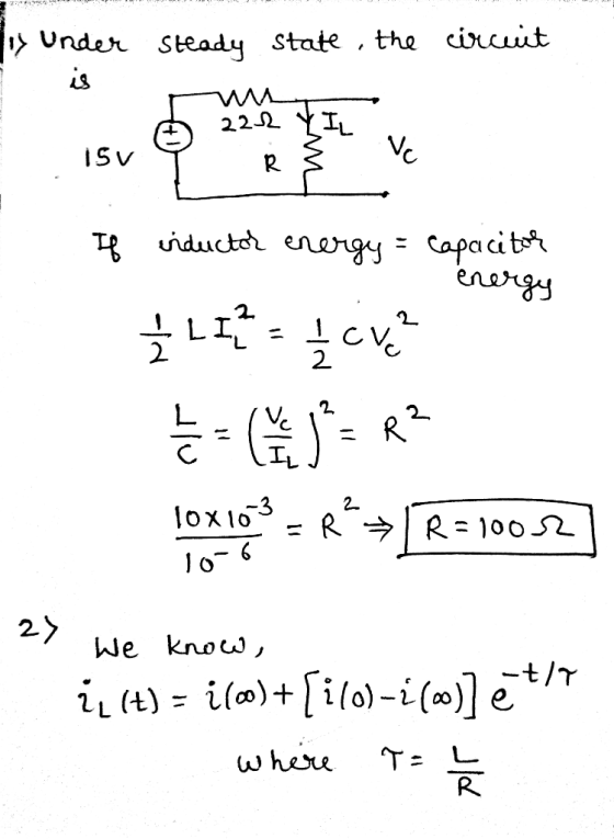
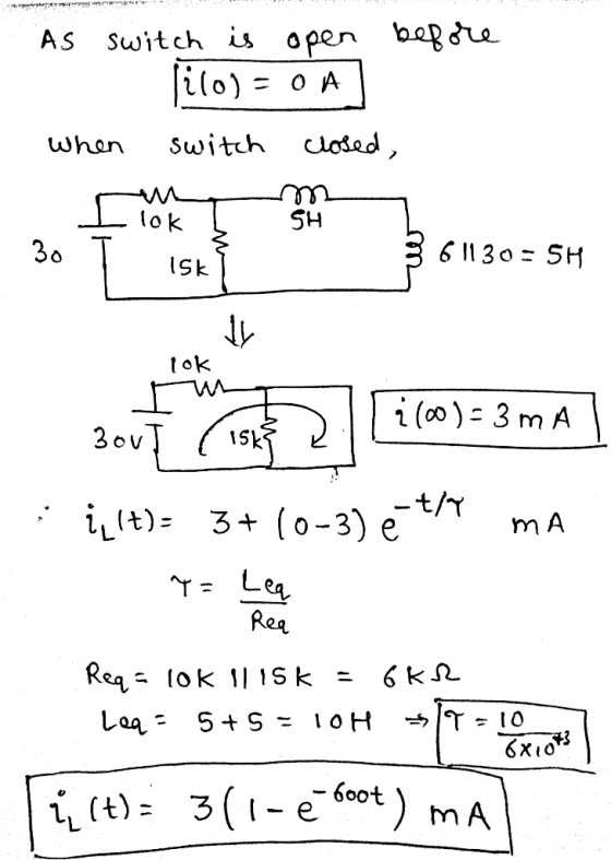
 Question 2 For the network in Figure Q2. (a) Find the mathematical expressions for the voltag e yL and the current İL following the (9 marks) (4 marks) closing of the switch. (b) Sketch the waveforms of yi and i, obtained in part (a). (c) Determine the mathematical expression for the voltage vis following the closing of (2 marks) the switch, and sketch the waveform. ム 5 H 10 k12 16H L3引30H 30V Figure Q2
1. An RL circuit comprised of one resistor and one inductor is shown in the figure...
 1. An RL circuit comprised of one resistor and one inductor is shown in the figure below. The resistor and inductor are connected to a source of emf with negligible internal resistance by a switch a. The emf for this circuit is 12.0 V. The resistance of the resistor is 0.35 12, and the inductance of the inductor is 53 mH. For the circuit below: a. Sketch the graph of current through the inductor as a function of time after...
1. An RL circuit comprised of one resistor and one inductor is shown in the figure below. The resistor and inductor...
 1. An RL circuit comprised of one resistor and one inductor is shown in the figure below. The resistor and inductor are connected to a source of emf with negligible internal resistance by a switch a. The emf for this circuit is 12.0 V. The resistance of the resistor is 0.35 , and the inductance of the inductor is 53 mH. For the circuit below: a. Sketch the graph of current through the inductor as a function of time after...
Questions and answers are here, need solution process. 3. a) For the circuit shown in Figure...
 Questions and answers are here, need solution process.
3. a) For the circuit shown in Figure Q3 (a): i) Find the mathematical expression for the transient behaviour of the voltage 6 vc across the capacitor and the current ic when the switch is moved into position 1 at t- 0 s ii) Find the mathematical expression for the response of vc and ic if the switch 4 is moved into position 2 at t charging phase) τ (where τ is...
Questions and answers are here, need solution process.
3. a) For the circuit shown in Figure Q3 (a): i) Find the mathematical expression for the transient behaviour of the voltage 6 vc across the capacitor and the current ic when the switch is moved into position 1 at t- 0 s ii) Find the mathematical expression for the response of vc and ic if the switch 4 is moved into position 2 at t charging phase) τ (where τ is...
Please help me all steps. 1- Set up the circuit as shown in figure (7). Then...
 Please help me all steps.
1- Set up the circuit as shown in figure (7). Then 330 resistor is to limit the maximum current reached. Then 100 resistor is to display the current waveform on the oscilloscope. 0.033k Chi (Voltage) 10mH Ch2 (Current) 0.01K common Figure (7) 2- Adjust the wave generator to give a peak voltage of 10 V square wave at 250Hz (Period is 4msec and Pulse Width is 2msec). Set the OSC as follows: Time base: 1...
Please help me all steps.
1- Set up the circuit as shown in figure (7). Then 330 resistor is to limit the maximum current reached. Then 100 resistor is to display the current waveform on the oscilloscope. 0.033k Chi (Voltage) 10mH Ch2 (Current) 0.01K common Figure (7) 2- Adjust the wave generator to give a peak voltage of 10 V square wave at 250Hz (Period is 4msec and Pulse Width is 2msec). Set the OSC as follows: Time base: 1...
Question B2 Figure 8 shows a DC electric circuit with a 2-way switch. The capacitor is...
 Question B2 Figure 8 shows a DC electric circuit with a 2-way switch. The capacitor is initially not charged. At t= Os, switch is at position and the capacitor is then charged up 1000 Position1 RT Position2 (20V R 500 0.02F (NV Figure 8 (a) Whent > sec, the capacitor is charged through R, to steady state, 0 Find the complete response of y(t) fort > 0s. (5 marks) (m) Sketch the response of (t) for t> Os. (3 marks)...
PART A Question 1 4 Figure Q1 Consider the reversible thermal cycle undergone by an ideal gas shown in Fig. Q1. The cycle is formed by two isobars and two isotherms. (a) Calculate the total work...
 PART A Question 1 4 Figure Q1 Consider the reversible thermal cycle undergone by an ideal gas shown in Fig. Q1. The cycle is formed by two isobars and two isotherms. (a) Calculate the total work involved in the cycle. Explain whether the gas does work on its surroundings [5 marks] b) Calculate the net heat exchange involved in path 1-3. Express your result in terms of the pressure and volume of the gas. [5 marks] (c) Make a plot...
An analogue amplifier circuit is shown in Figure 1 below. VDD Q5 15V JL - Vout...
 An analogue amplifier circuit is shown in Figure 1 below. VDD Q5 15V JL - Vout Irer RI Vina JET T7T Figure 1 Integrated amplifier circuit. Circuit Data: Vpp = 15 V, IREF = I1 = I2 = 1.0 mA Transistor Data: Q1: NMOS, un Cox = 80 A/V?, W/L = 100 um/0.8 um, Vtn = 0.8 V, L = 0.10 um/V Q2: NPN BJT, B = 100, Vbe = 0.7 V, VA = 150 V Q3, Q4: NMOS, un...
MATLAB question. Please answer all the questions and also upload the code by MATLAB. Thanks. Down vote if no code provided. For the circuit shown above, at the moment t = 0, the switch is closed, fin...
 MATLAB question. Please answer all the questions and also upload
the code by MATLAB. Thanks. Down vote if no code provided.
For the circuit shown above, at the moment t = 0, the switch is closed, find w(t) for 120, No energy is stored in the capacitor and inductor at moment t-0 1. Write the dynamic model for RLC circuit after t> 0? a. Show all vour work and calculations b. Write down the characteristic equation of the transfer function...
MATLAB question. Please answer all the questions and also upload
the code by MATLAB. Thanks. Down vote if no code provided.
For the circuit shown above, at the moment t = 0, the switch is closed, find w(t) for 120, No energy is stored in the capacitor and inductor at moment t-0 1. Write the dynamic model for RLC circuit after t> 0? a. Show all vour work and calculations b. Write down the characteristic equation of the transfer function...
 Question 2 For the network in Figure Q2. (a) Find the mathematical expressions for the voltag e yL and the current İL following the (9 marks) (4 marks) closing of the switch. (b) Sketch the waveforms of yi and i, obtained in part (a). (c) Determine the mathematical expression for the voltage vis following the closing of (2 marks) the switch, and sketch the waveform. ム 5 H 10 k12 16H L3引30H 30V Figure Q2
 1. An RL circuit comprised of one resistor and one inductor is shown in the figure below. The resistor and inductor are connected to a source of emf with negligible internal resistance by a switch a. The emf for this circuit is 12.0 V. The resistance of the resistor is 0.35 12, and the inductance of the inductor is 53 mH. For the circuit below: a. Sketch the graph of current through the inductor as a function of time after...
 1. An RL circuit comprised of one resistor and one inductor is shown in the figure below. The resistor and inductor are connected to a source of emf with negligible internal resistance by a switch a. The emf for this circuit is 12.0 V. The resistance of the resistor is 0.35 12, and the inductance of the inductor is 53 mH. For the circuit below: a. Sketch the graph of current through the inductor as a function of time after...
 1. An RL circuit comprised of one resistor and one inductor is shown in the figure below. The resistor and inductor are connected to a source of emf with negligible internal resistance by a switch a. The emf for this circuit is 12.0 V. The resistance of the resistor is 0.35 , and the inductance of the inductor is 53 mH. For the circuit below: a. Sketch the graph of current through the inductor as a function of time after...
 Questions and answers are here, need solution process.
3. a) For the circuit shown in Figure Q3 (a): i) Find the mathematical expression for the transient behaviour of the voltage 6 vc across the capacitor and the current ic when the switch is moved into position 1 at t- 0 s ii) Find the mathematical expression for the response of vc and ic if the switch 4 is moved into position 2 at t charging phase) τ (where τ is...
Questions and answers are here, need solution process.
3. a) For the circuit shown in Figure Q3 (a): i) Find the mathematical expression for the transient behaviour of the voltage 6 vc across the capacitor and the current ic when the switch is moved into position 1 at t- 0 s ii) Find the mathematical expression for the response of vc and ic if the switch 4 is moved into position 2 at t charging phase) τ (where τ is...
 Please help me all steps.
1- Set up the circuit as shown in figure (7). Then 330 resistor is to limit the maximum current reached. Then 100 resistor is to display the current waveform on the oscilloscope. 0.033k Chi (Voltage) 10mH Ch2 (Current) 0.01K common Figure (7) 2- Adjust the wave generator to give a peak voltage of 10 V square wave at 250Hz (Period is 4msec and Pulse Width is 2msec). Set the OSC as follows: Time base: 1...
Please help me all steps.
1- Set up the circuit as shown in figure (7). Then 330 resistor is to limit the maximum current reached. Then 100 resistor is to display the current waveform on the oscilloscope. 0.033k Chi (Voltage) 10mH Ch2 (Current) 0.01K common Figure (7) 2- Adjust the wave generator to give a peak voltage of 10 V square wave at 250Hz (Period is 4msec and Pulse Width is 2msec). Set the OSC as follows: Time base: 1...
 Question B2 Figure 8 shows a DC electric circuit with a 2-way switch. The capacitor is initially not charged. At t= Os, switch is at position and the capacitor is then charged up 1000 Position1 RT Position2 (20V R 500 0.02F (NV Figure 8 (a) Whent > sec, the capacitor is charged through R, to steady state, 0 Find the complete response of y(t) fort > 0s. (5 marks) (m) Sketch the response of (t) for t> Os. (3 marks)...
 PART A Question 1 4 Figure Q1 Consider the reversible thermal cycle undergone by an ideal gas shown in Fig. Q1. The cycle is formed by two isobars and two isotherms. (a) Calculate the total work involved in the cycle. Explain whether the gas does work on its surroundings [5 marks] b) Calculate the net heat exchange involved in path 1-3. Express your result in terms of the pressure and volume of the gas. [5 marks] (c) Make a plot...
 An analogue amplifier circuit is shown in Figure 1 below. VDD Q5 15V JL - Vout Irer RI Vina JET T7T Figure 1 Integrated amplifier circuit. Circuit Data: Vpp = 15 V, IREF = I1 = I2 = 1.0 mA Transistor Data: Q1: NMOS, un Cox = 80 A/V?, W/L = 100 um/0.8 um, Vtn = 0.8 V, L = 0.10 um/V Q2: NPN BJT, B = 100, Vbe = 0.7 V, VA = 150 V Q3, Q4: NMOS, un...
 MATLAB question. Please answer all the questions and also upload
the code by MATLAB. Thanks. Down vote if no code provided.
For the circuit shown above, at the moment t = 0, the switch is closed, find w(t) for 120, No energy is stored in the capacitor and inductor at moment t-0 1. Write the dynamic model for RLC circuit after t> 0? a. Show all vour work and calculations b. Write down the characteristic equation of the transfer function...
MATLAB question. Please answer all the questions and also upload
the code by MATLAB. Thanks. Down vote if no code provided.
For the circuit shown above, at the moment t = 0, the switch is closed, find w(t) for 120, No energy is stored in the capacitor and inductor at moment t-0 1. Write the dynamic model for RLC circuit after t> 0? a. Show all vour work and calculations b. Write down the characteristic equation of the transfer function...
Most questions answered within 3 hours.
-
I create an address book where the user enters the name, phone
and email in the...
asked 36 seconds ago -
The production capacity for acrylonitrile
(C3H3N) in the United States exceeds 2
million pounds per year....
asked 8 minutes ago -
explain and comment out your answer
43. How many address lines are required to address a...
asked 14 minutes ago -
A sample of 45 observations is selected from a normal
population. The sample mean is 49,...
asked 29 minutes ago -
A construction company is planning to bid on a building
contract. The bid costs the company...
asked 26 minutes ago -
A firm operating in a purely competitive environment is faced
with a market price of $250....
asked 33 minutes ago -
•Let’s say someone claims the average population size is
600 feet squared and the housing authority...
asked 40 minutes ago -
Cynaide is a deadly poison that blocks the last step in the
electron transport chain of...
asked 45 minutes ago -
Your friend tells you that there is a vending machine on campus
that dispenses M&M packs...
asked 1 hour ago -
What advantages are there to using piperidine rather than
hydroxide as a base?
asked 58 minutes ago -
7. The life of a Freeze Breeze electric fan is normally
distributed with a mean 4...
asked 1 hour ago -
1. A 751 mL NaCl solution is diluted to a volume of 1.06 L and a...
asked 1 hour ago