A system consists of two plants connected by a transmission line and a load that is...
A system consists of two plants connected by a transmission line and a load that is located at plant 2. Data for the loss equation consists of the information that 100 MW transmitted from plant 1 to the load results in a loss of 10 MW and

where B11 is the only non-zero loss coefficient. Assume that the
incremental fuelcosts can be approximated by the following
equations:
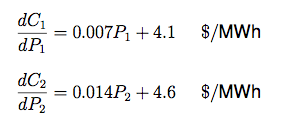
Find the required generation for each plant and the power received by the load when ? for the system is $6 per Mwh.
Homework Answers


Add Answer to:
A system consists of two plants connected by a transmission line
and a load that is...
A transmission line consists of two parts, the first part has a rating of 0.15 dB...
A transmission line consists of two parts, the first part has a rating of 0.15 dB / m with a length of 20 m. The second part has a length of 10 m with a rating of 0.959 dB / m and an impedance of 50 ohms. The reflected coefficient on the transmission line connection between the two parts is 0.3. The end of the second channel is connected with a load of 100 + j100 ohms. If the power...
Problem 2 The fuel-cost function in $/h of two thermal plants are ?1 = 320 +...
 Problem 2 The fuel-cost function in $/h of two thermal plants
are ?1 = 320 + 6.2?1 + 0.004?1 2 , ?2 = 200 + 6.0?2 + 0.003?2 2 ,
where ?1 and ?2 are in MW. Plant outputs are subject to the
following limits (in MW)
Problem 2 The fuel-cost function in $/h of two thermal plants are C1 = 320 +6.2P2 +0.004P], C2 = 200 +6.0P2 + 0.003P2, where P and P2 are in MW. Plant outputs are...
Problem 2 The fuel-cost function in $/h of two thermal plants
are ?1 = 320 + 6.2?1 + 0.004?1 2 , ?2 = 200 + 6.0?2 + 0.003?2 2 ,
where ?1 and ?2 are in MW. Plant outputs are subject to the
following limits (in MW)
Problem 2 The fuel-cost function in $/h of two thermal plants are C1 = 320 +6.2P2 +0.004P], C2 = 200 +6.0P2 + 0.003P2, where P and P2 are in MW. Plant outputs are...
A balanced A-connected load of Z,=12+39.0 12 is connected to a power supply via a transmission...
 A balanced A-connected load of Z,=12+39.0 12 is connected to a power supply via a transmission line with impedance of Zrl=0.6+j2.5 12, find Transmission Lines o 20820 V AC 2084(0–240°) v umaza 10 AC 2084(0-120°) v mm | za | Three-Phase 208 V, 60 HZ Power Supply Three-Phase A-Connected Balanced Load @@OGO E the load line and phase voltages (magnitude and angle), the load line and phase currents (magnitude and angle), the total load's real, reactive, and apparent powers, the...
A 3-phase 138-kv transmission line is connected to a 49 MW load at .85 lagging power...
 A 3-phase 138-kv transmission line is connected to a 49 MW load at .85 lagging power factor. The line constants of the 52-mile long line are Z = 95 L 78 degree ohm and Y=.001 L90 degree S. Using the nominal T Circuit representation, calculate the A, B, C, and D constants of the line Sending-end voltage Sending-end current Sending-end power factor Efficiency of transmission
A transmission line with characteristic impedance of 100 ? is connected to a 200+j400 ? load....
A transmission line with characteristic impedance of 100 ? is connected to a 200+j400 ? load. Use Smith chart to calculate (i) standing wave ratio (ii) reflection coefficient (iii) lengths and locations of a short circuited shunt stub to match the load to the transmission line.
A balanced three-phase delta-connected load is connected to a balanced three-phase delta-connected source via a transmission...
A balanced three-phase delta-connected load is connected to a balanced three-phase delta-connected source via a transmission line. The line-line voltage for the source is 100∟0° V/phase and the impedance of load is (27 + j18) Ω/phase. The transmission line has an impedance of (1 + j4) Ω/line. a) Draw the complete schematic of the power system showing the location of wattmeters. (Two-Wattmeter system is considered for this problem). Phase “a” could be considered as a reference phase. b) What must...
The six-bus system shown in Figure 1 will be simulated using MATLAB. Transmission line data and b...
 The six-bus system shown in Figure 1 will be simulated using MATLAB. Transmission line data and bus data are given in Tables 1 and 2 respectively. The transmission line data are calculated on 100 MVA base and 230 (line-to-line) kV base for generator. Tasks: 1. Determine the network admittance matrix Y 2. Find the load flow solution using Gauss-Seidel/Newton Raphson method until first iteration by manual calculation. Use Maltab software to solve power flow problem using Gauss-Seidel method. Find the...
A generator is connected to a transmission line system that is shown below. The system consists o...
 please follow instruction and solve every task in detail, thank
you very much!
A generator is connected to a transmission line system that is shown below. The system consists of two transmission lines, each with a characteristic impedance of 75 [2], connected to a load impedance of 75 [2]. These two lines are then fed by a single main feed line having a characteristic impedance 75 [2], which is fed by the generator (not shown). It is desired to have...
please follow instruction and solve every task in detail, thank
you very much!
A generator is connected to a transmission line system that is shown below. The system consists of two transmission lines, each with a characteristic impedance of 75 [2], connected to a load impedance of 75 [2]. These two lines are then fed by a single main feed line having a characteristic impedance 75 [2], which is fed by the generator (not shown). It is desired to have...
Qustion 2.120 marks) a) Figure I below shows a system with plant-I and plant-2 connected to bus-1 and bus-2 respectively. There are two loads and 3 branches. The bus-I is the reference bus with 1...
 Qustion 2.120 marks) a) Figure I below shows a system with plant-I and plant-2 connected to bus-1 and bus-2 respectively. There are two loads and 3 branches. The bus-I is the reference bus with 1.040° pu voltage. Base MVA is 100 If the branch currents and branch impedance values are as follows -2.5-j0.50pu -2-j040 pu I 1.5-j0.3 pu Calculate: 7-0.05+j0.20 pu -0.02+j0.08 pu Z 0.025+j0.10 pu i. Current distribution factors (4 marks) ii. Power factor angles at bus 1 and...
Question L(20 marks) The variable operating costs of three generators a power system connected in are...
 Question L(20 marks) The variable operating costs of three generators a power system connected in are as follows: The generator limits are: 100 s P S 400 MW 150 S P2 s 500 MW The total transmission losses for the power system are given by: B=1.5×10⁻⁴ P/ + 2 x 10-sPgPg + 3 × 10-sp/ Mw Given λ 16.00 SMfw hr Determine: i. Output of each unit (6 marks) ii. Total transmission losses (3 marks) ii. Total load demand (2...
 Problem 2 The fuel-cost function in $/h of two thermal plants
are ?1 = 320 + 6.2?1 + 0.004?1 2 , ?2 = 200 + 6.0?2 + 0.003?2 2 ,
where ?1 and ?2 are in MW. Plant outputs are subject to the
following limits (in MW)
Problem 2 The fuel-cost function in $/h of two thermal plants are C1 = 320 +6.2P2 +0.004P], C2 = 200 +6.0P2 + 0.003P2, where P and P2 are in MW. Plant outputs are...
Problem 2 The fuel-cost function in $/h of two thermal plants
are ?1 = 320 + 6.2?1 + 0.004?1 2 , ?2 = 200 + 6.0?2 + 0.003?2 2 ,
where ?1 and ?2 are in MW. Plant outputs are subject to the
following limits (in MW)
Problem 2 The fuel-cost function in $/h of two thermal plants are C1 = 320 +6.2P2 +0.004P], C2 = 200 +6.0P2 + 0.003P2, where P and P2 are in MW. Plant outputs are...
 A balanced A-connected load of Z,=12+39.0 12 is connected to a power supply via a transmission line with impedance of Zrl=0.6+j2.5 12, find Transmission Lines o 20820 V AC 2084(0–240°) v umaza 10 AC 2084(0-120°) v mm | za | Three-Phase 208 V, 60 HZ Power Supply Three-Phase A-Connected Balanced Load @@OGO E the load line and phase voltages (magnitude and angle), the load line and phase currents (magnitude and angle), the total load's real, reactive, and apparent powers, the...
 A 3-phase 138-kv transmission line is connected to a 49 MW load at .85 lagging power factor. The line constants of the 52-mile long line are Z = 95 L 78 degree ohm and Y=.001 L90 degree S. Using the nominal T Circuit representation, calculate the A, B, C, and D constants of the line Sending-end voltage Sending-end current Sending-end power factor Efficiency of transmission
 The six-bus system shown in Figure 1 will be simulated using MATLAB. Transmission line data and bus data are given in Tables 1 and 2 respectively. The transmission line data are calculated on 100 MVA base and 230 (line-to-line) kV base for generator. Tasks: 1. Determine the network admittance matrix Y 2. Find the load flow solution using Gauss-Seidel/Newton Raphson method until first iteration by manual calculation. Use Maltab software to solve power flow problem using Gauss-Seidel method. Find the...
 please follow instruction and solve every task in detail, thank
you very much!
A generator is connected to a transmission line system that is shown below. The system consists of two transmission lines, each with a characteristic impedance of 75 [2], connected to a load impedance of 75 [2]. These two lines are then fed by a single main feed line having a characteristic impedance 75 [2], which is fed by the generator (not shown). It is desired to have...
please follow instruction and solve every task in detail, thank
you very much!
A generator is connected to a transmission line system that is shown below. The system consists of two transmission lines, each with a characteristic impedance of 75 [2], connected to a load impedance of 75 [2]. These two lines are then fed by a single main feed line having a characteristic impedance 75 [2], which is fed by the generator (not shown). It is desired to have...
 Qustion 2.120 marks) a) Figure I below shows a system with plant-I and plant-2 connected to bus-1 and bus-2 respectively. There are two loads and 3 branches. The bus-I is the reference bus with 1.040° pu voltage. Base MVA is 100 If the branch currents and branch impedance values are as follows -2.5-j0.50pu -2-j040 pu I 1.5-j0.3 pu Calculate: 7-0.05+j0.20 pu -0.02+j0.08 pu Z 0.025+j0.10 pu i. Current distribution factors (4 marks) ii. Power factor angles at bus 1 and...
 Question L(20 marks) The variable operating costs of three generators a power system connected in are as follows: The generator limits are: 100 s P S 400 MW 150 S P2 s 500 MW The total transmission losses for the power system are given by: B=1.5×10⁻⁴ P/ + 2 x 10-sPgPg + 3 × 10-sp/ Mw Given λ 16.00 SMfw hr Determine: i. Output of each unit (6 marks) ii. Total transmission losses (3 marks) ii. Total load demand (2...
Most questions answered within 3 hours.
-
lease solve all the
questions, don't need to explanations
Q1 - All animal
species have general...
asked 1 hour ago -
Business Phasing
1.Discuss the logical progression for growing a business, which
starts from the initial idea...
asked 1 hour ago -
Modify
When executing on the command line having only
this program name, the program will accept...
asked 2 hours ago -
Kenny Electric Company's noncallable bonds were issued several
years ago and now have 20 years to...
asked 2 hours ago -
find H(e^Jtheta) at theta= 0, pi/10, pi/20, pi/2 for
the following:
a) H(e^Jtheta)= 1+e^Jtheta
b) H(e^Jtheta)=...
asked 3 hours ago -
Home Corporation will open a new store on January 1. Based on
experience from its other...
asked 3 hours ago -
In a neoclassical model, use the IS-LM to analyze the effect of
a permanent money supply...
asked 4 hours ago -
An electron passes through a point 2.67 cm from a long straight
wire as it moves...
asked 4 hours ago -
A grammar is a 4-tuple G, G = (Ν, Σ, Π, Σ, S) where, Ν is...
asked 5 hours ago -
In this part, calculate the present values. Use the Excel PV
function to compute the present...
asked 5 hours ago -
Part 1. Primitive Types, Sorting, Recursion for
Homework.java
a) Implement the static method initializeArray that receives...
asked 6 hours ago -
Using C++, build a sorter that can rank a sequence of numbers in
a descending order....
asked 6 hours ago