shear force and bending moment diagrams only.
Homework Answers
Add Answer to:
shear force and bending moment diagrams only.
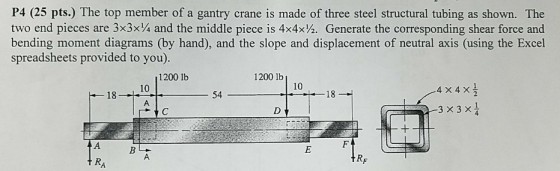
P4 (25 pts.) The top member of a gantry...
Draw the axial force, shear force, and bending moment diagramsfor each member of the frame....
 Draw the axial force, shear force, and bending moment diagrams
for each member of the frame. Additionally, determine the axial
force, shear force, and bending moment considering the section
located on member BC, 1m from C
Draw the axial force, shear force, and bending moment diagrams
for each member of the frame. Additionally, determine the axial
force, shear force, and bending moment considering the section
located on member BC, 1m from C
4. For the beam and loading shown, draw the shear force and bending moment diagrams and...
 4. For the beam and loading shown, draw the shear force and bending moment diagrams and determine the maximum bending and shear force and their locations. 20 KN 40 KN B D 250 mm |--2.5 m- 3m-4-2 m 80 mm 5. For the beam and loading shown, draw the shear force and bending moment diagrams and determine the maximum bending and shear force and their locations. 50 KN
Problem 4. Sketch complete shear force and bending moment diagrams for the beam below. (30 Points)...
 Problem 4. Sketch complete shear force and bending moment diagrams for the beam below. (30 Points) 2000 lb V (lb) 0 M(ft lb) 0
Please help? Construct the shear force and bending moment diagrams for the beam shown by the...
 Please help?
Construct the shear force and bending moment diagrams for the
beam shown by the area method.
Neglect the weight of the beam.
200 lb/ft Hinge 2 ft FIG. P4.41
Please help?
Construct the shear force and bending moment diagrams for the
beam shown by the area method.
Neglect the weight of the beam.
200 lb/ft Hinge 2 ft FIG. P4.41
Answer clearly show each step and freebody diagrams 3. Construct the complete shear force and bending...
 Answer clearly show each step and freebody
diagrams
3. Construct the complete shear force and bending moment diagrams for the beam shown below. Axes should be labeled and shown units. Identify the magnitude and location of the maximum bending moment (positive or negative) 400 lb/ft В 4. Construct the complete shear force and bending moment diagrams for the beam shown below. Axes should be labeled and shown units. Identify the magnitude and location of the maximum bending moment (positive or...
Answer clearly show each step and freebody
diagrams
3. Construct the complete shear force and bending moment diagrams for the beam shown below. Axes should be labeled and shown units. Identify the magnitude and location of the maximum bending moment (positive or negative) 400 lb/ft В 4. Construct the complete shear force and bending moment diagrams for the beam shown below. Axes should be labeled and shown units. Identify the magnitude and location of the maximum bending moment (positive or...
Problem 7 Draw the complete axial force, shear force, andbending moment diagrams for each member...
 Problem 7 Draw the complete axial force, shear force, and
bending moment diagrams for each member of the frame shown in
Figure 7. Assume A is fixed, the joint at B is a hinge, and support
C is a roller.
Problem 7 Draw the complete axial force, shear force, and
bending moment diagrams for each member of the frame shown in
Figure 7. Assume A is fixed, the joint at B is a hinge, and support
C is a roller.
QUIZ 3 STATICS 5/4/2018 201 in-class) Draw shear force and bending moment diagrams for the uniform...
 QUIZ 3 STATICS 5/4/2018 201 in-class) Draw shear force and bending moment diagrams for the uniform beam ABC. Find the maximum bending moment and its location on the beam. 60 Ib/ft 180 lb ft 200lb
For the beam shown in Fig. 9.3, draw the shear force and bending moment diagrams. Use...
 For the beam shown in Fig. 9.3, draw the shear force and bending moment diagrams. Use the area method that relies on the relationships between loading and shear force and between shear force and bending moment. Indicate the slope of the shear force diagram at locations A, B, C, and D using the load information in Fig. 9.3. Indicate the slope of the bending moment diagram at the same four locations using information from the shear force diagram. | 6...
Construct the shear and moment diagrams for the beam subjected to the concentrated force and coup...
 Construct the shear and moment diagrams for the beam subjected to the concentrated force and couple and the triangular load. After you have the diagrams, answer the questions as a check on your work 270 lb/ft 1580 lb-ft 2" 3 1220 lb when x 1.2 ft, V = When x4.7 ft, V- when x = 13.8 ft, V = when x = 18.2 ft, V = 2 lb-ft 4 lb-ft 6 lb-ft lb-ft The maximum (absolute value) shear force in...
4) Draw the shear force and bending moment diagrams for the beam subjected to the loading...
 4) Draw the shear force and bending moment diagrams for the beam subjected to the loading shown. 30) KN SUKN
 Draw the axial force, shear force, and bending moment diagrams
for each member of the frame. Additionally, determine the axial
force, shear force, and bending moment considering the section
located on member BC, 1m from C
Draw the axial force, shear force, and bending moment diagrams
for each member of the frame. Additionally, determine the axial
force, shear force, and bending moment considering the section
located on member BC, 1m from C
 4. For the beam and loading shown, draw the shear force and bending moment diagrams and determine the maximum bending and shear force and their locations. 20 KN 40 KN B D 250 mm |--2.5 m- 3m-4-2 m 80 mm 5. For the beam and loading shown, draw the shear force and bending moment diagrams and determine the maximum bending and shear force and their locations. 50 KN
 Problem 4. Sketch complete shear force and bending moment diagrams for the beam below. (30 Points) 2000 lb V (lb) 0 M(ft lb) 0
 Please help?
Construct the shear force and bending moment diagrams for the
beam shown by the area method.
Neglect the weight of the beam.
200 lb/ft Hinge 2 ft FIG. P4.41
Please help?
Construct the shear force and bending moment diagrams for the
beam shown by the area method.
Neglect the weight of the beam.
200 lb/ft Hinge 2 ft FIG. P4.41
 Answer clearly show each step and freebody
diagrams
3. Construct the complete shear force and bending moment diagrams for the beam shown below. Axes should be labeled and shown units. Identify the magnitude and location of the maximum bending moment (positive or negative) 400 lb/ft В 4. Construct the complete shear force and bending moment diagrams for the beam shown below. Axes should be labeled and shown units. Identify the magnitude and location of the maximum bending moment (positive or...
Answer clearly show each step and freebody
diagrams
3. Construct the complete shear force and bending moment diagrams for the beam shown below. Axes should be labeled and shown units. Identify the magnitude and location of the maximum bending moment (positive or negative) 400 lb/ft В 4. Construct the complete shear force and bending moment diagrams for the beam shown below. Axes should be labeled and shown units. Identify the magnitude and location of the maximum bending moment (positive or...
 Problem 7 Draw the complete axial force, shear force, and
bending moment diagrams for each member of the frame shown in
Figure 7. Assume A is fixed, the joint at B is a hinge, and support
C is a roller.
Problem 7 Draw the complete axial force, shear force, and
bending moment diagrams for each member of the frame shown in
Figure 7. Assume A is fixed, the joint at B is a hinge, and support
C is a roller.
 QUIZ 3 STATICS 5/4/2018 201 in-class) Draw shear force and bending moment diagrams for the uniform beam ABC. Find the maximum bending moment and its location on the beam. 60 Ib/ft 180 lb ft 200lb
 For the beam shown in Fig. 9.3, draw the shear force and bending moment diagrams. Use the area method that relies on the relationships between loading and shear force and between shear force and bending moment. Indicate the slope of the shear force diagram at locations A, B, C, and D using the load information in Fig. 9.3. Indicate the slope of the bending moment diagram at the same four locations using information from the shear force diagram. | 6...
 Construct the shear and moment diagrams for the beam subjected to the concentrated force and couple and the triangular load. After you have the diagrams, answer the questions as a check on your work 270 lb/ft 1580 lb-ft 2" 3 1220 lb when x 1.2 ft, V = When x4.7 ft, V- when x = 13.8 ft, V = when x = 18.2 ft, V = 2 lb-ft 4 lb-ft 6 lb-ft lb-ft The maximum (absolute value) shear force in...
 4) Draw the shear force and bending moment diagrams for the beam subjected to the loading shown. 30) KN SUKN
Most questions answered within 3 hours.
-
The Bahraini public budget experiences deficit in the last
seven years, what are procedures are taken...
asked 3 minutes ago -
You invested $30,000 in a mutual fund at the beginning of the
year when the NAV...
asked 7 minutes ago -
Would you expect the price elasticity of supply for guitars to
be more inelastic in the...
asked 9 minutes ago -
A snowmobile is originally at the point with position vector
30.1 m at 95.0° counterclockwise from...
asked 8 minutes ago -
MAN3240 Organizational Behavior
In one to two paragraphs
6.) How can understanding emotions make me more...
asked 17 minutes ago -
Identify one individual who, in your opinion, is an excellent
leader. List the qualities that this...
asked 14 minutes ago -
For the data set shown below, complete parts (a) through (d)
below. x 3 4 5...
asked 20 minutes ago -
A university administrator working in student housing wants to
determine if the percentage of students residing...
asked 34 minutes ago -
3). Describe human population growth that has occurred in the
past 400 years. Use terms learned...
asked 31 minutes ago -
A
projectile is blue at a target. The distance from the point of
impact to the...
asked 56 minutes ago -
Given a 32 bit processor, with 2 MB of physical RAM split into 512
frames. What...
asked 46 minutes ago -
What were the main rulings in the Supreme Court cases which are
Morgan v. Virginia (1946)...
asked 45 minutes ago