Please show all the necessary steps to get the answers

Homework Answers


Add Answer to:
Please show all the necessary steps to get the
answers
eo Figure 1.1 Show that the...
Please show all the necessary steps to get the answers For the electronics experts The following...
 Please show all the necessary steps to get the
answers
For the electronics experts The following VCO is used for direct FM generation. -) mt) (a) Explain its operation and list the advantages and disadvantages over the indirect method If the voltage variable capacitor is a reversed biased pn junction diode whose capacitance is related to the reverse biasing voltage v by Cy- (100/ 1+2v) p The capacitance Co- 200pF and L is adjusted for resonance at 5 MHz when...
Please show all the necessary steps to get the
answers
For the electronics experts The following VCO is used for direct FM generation. -) mt) (a) Explain its operation and list the advantages and disadvantages over the indirect method If the voltage variable capacitor is a reversed biased pn junction diode whose capacitance is related to the reverse biasing voltage v by Cy- (100/ 1+2v) p The capacitance Co- 200pF and L is adjusted for resonance at 5 MHz when...
Please show all the necessary steps to get the answers Answer Q5 A given DSB-LC transmitter...
 Please show all the necessary steps to get the
answers
Answer
Q5 A given DSB-LC transmitter develops an unmodulated power output of 100W across a 50 ? resistive load. When a sinusoidal test tone with a peak amplitude of 5.0 V is applied to the input of the modulator, it is found that the average power output increases by 50% under these conditions. Determine (a) (b) (c) (d) (e) The average power output in each sideband. The modulation index. The...
Please show all the necessary steps to get the
answers
Answer
Q5 A given DSB-LC transmitter develops an unmodulated power output of 100W across a 50 ? resistive load. When a sinusoidal test tone with a peak amplitude of 5.0 V is applied to the input of the modulator, it is found that the average power output increases by 50% under these conditions. Determine (a) (b) (c) (d) (e) The average power output in each sideband. The modulation index. The...
For the circuit in Figure 1, determine the output voltage eo in relation to the input e 10.0 20.0...
 For the circuit in Figure 1, determine the output voltage eo in relation to the input e 10.0 20.0 50.0 100.0 200.0 500.0 1,000.0 2,000.0 5,000.0 10,000.0 1.00 1.00 0.97 0.92 0.71 0.37 0.21 0.10 0.04 0.02 Figure 1 The above table was obtained for a 1.0-volt sine-wane input. Find the value of the resistor R if the capacitance C0.033uF in the RC filter
For the circuit in Figure 1, determine the output voltage eo in relation to the input...
For the circuit in Figure 1, determine the output voltage eo in relation to the input e 10.0 20.0 50.0 100.0 200.0 500.0 1,000.0 2,000.0 5,000.0 10,000.0 1.00 1.00 0.97 0.92 0.71 0.37 0.21 0.10 0.04 0.02 Figure 1 The above table was obtained for a 1.0-volt sine-wane input. Find the value of the resistor R if the capacitance C0.033uF in the RC filter
For the circuit in Figure 1, determine the output voltage eo in relation to the input...
Figure 3 Transistor amplifire circuit with source Vs and load R b) For the BJT switching...
 Figure 3 Transistor amplifire circuit with source Vs and load R b) For the BJT switching circuit shown in Figure 4, i) Calculate the value of Ra so that the transistor is operating in saturation when switched on if the value of Rc is 3.9 kn. ii) What will the output voltage be for the applied input signal voltage shown if Vcet IS 0.2V? 5 V Re o V 5 V B 100 OV Figure 4 BUT switching circuit with...
Please clear step by step and correct answers thumb up An RL circuit network is shown...
 Please clear step by step and correct answers thumb
up
An RL circuit network is shown below in Figure 2. + Vri(t) W R1 vs(t) R2 Figure 2 RL circuir network 1. If the system input is the voltage of power source (t) and the system output is VRI(!) (voltage across RI), write the transfer function T/s) (Do not plug in any detail value) (10 point) Use R1-19, R2-122, L=1H and assume zero initial condition for all following questions, 2....
Please clear step by step and correct answers thumb
up
An RL circuit network is shown below in Figure 2. + Vri(t) W R1 vs(t) R2 Figure 2 RL circuir network 1. If the system input is the voltage of power source (t) and the system output is VRI(!) (voltage across RI), write the transfer function T/s) (Do not plug in any detail value) (10 point) Use R1-19, R2-122, L=1H and assume zero initial condition for all following questions, 2....
QUESTION 5 a) Determine the value of current A in Figure Q5 by using Thevenin Theorem....
 QUESTION 5 a) Determine the value of current A in Figure Q5 by using Thevenin Theorem. Solve VH using superposition theorem. (15 marks) b) State the value of Ri should have to allow maximum power to be delivered to it. ( mark) e) Calculate the voltage, current and power at the load, R when maximum power is delivered to it. (6 marks) d) Show that the efficiency in term of input and output power of the circuit is 50 %...
Show all the steps of the design cycle (as described in class) to create a combinational...
 Show all the steps of the design cycle (as described in class) to create a combinational circuit with three inputs (a, b,c) and one output (T). Your final answer should be the circuit diagram of your design, but you must show all previous steps to get to the final answer. 4. Circuit Behavior: your design circuit should output a 1 when the binary value of the inputs is less than 3. The output is O otherwise.
Show all your work and final answers on these pages. Attach the requested graphs. Background for ...
 solve questions 4,5,6 please. thanks
Show all your work and final answers on these pages. Attach the requested graphs. Background for Laboratory Experiment 6 In Experiment 6, you will study the dynamic behavior of an electroacoustic system (or speaker). The background for this Pre-Lab is in Section 6.7.5 in the textbook. A physical model of the electroacoustic system is shown in the figure below. Speaker enclosure Magnet The motion of the center of the speaker cone is x. The motion...
solve questions 4,5,6 please. thanks
Show all your work and final answers on these pages. Attach the requested graphs. Background for Laboratory Experiment 6 In Experiment 6, you will study the dynamic behavior of an electroacoustic system (or speaker). The background for this Pre-Lab is in Section 6.7.5 in the textbook. A physical model of the electroacoustic system is shown in the figure below. Speaker enclosure Magnet The motion of the center of the speaker cone is x. The motion...
1. Consider the circuit shown below. Cl e, (0) c, e。(t) Find the transfer function below using t...
 Please help with this dynamics circuit
analysis.
Please show work and explain.
Thank you!!
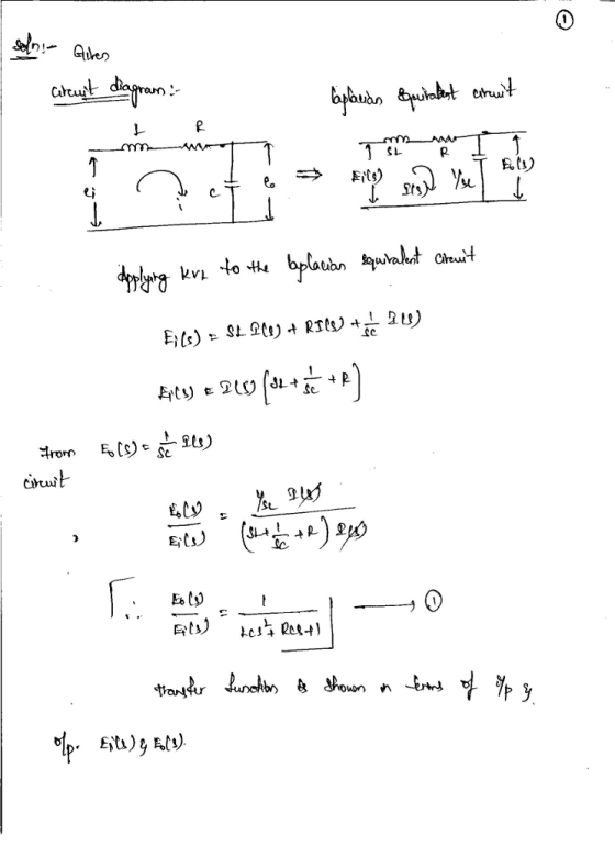
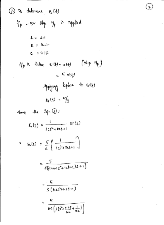
1. Consider the circuit shown below. Cl e, (0) c, e。(t) Find the transfer function below using time-domain and impedance methods. (a) Determine the differential equation for the relationship between eo(1) and e(1) (b) Find the transfer function E, (s)/E,(s) and determine the system time constant in terms of the circuit element values C, C, and R 17 2 (c) Find the transfer function E, (s)/E,...
Please help with this dynamics circuit
analysis.
Please show work and explain.
Thank you!!
1. Consider the circuit shown below. Cl e, (0) c, e。(t) Find the transfer function below using time-domain and impedance methods. (a) Determine the differential equation for the relationship between eo(1) and e(1) (b) Find the transfer function E, (s)/E,(s) and determine the system time constant in terms of the circuit element values C, C, and R 17 2 (c) Find the transfer function E, (s)/E,...
Please show all steps QUESTION 2 Given the circuit in Figure 2,C 0.4F. a) Find the...
 Please show all steps
QUESTION 2 Given the circuit in Figure 2,C 0.4F. a) Find the transfer function H(s) VoUT VIN b) Identify the gain K of the device, as well as all poles and zeroes. c) Given a complex frequency of s 2+ j and an input VN 0.1, find VouT 6 H 12 Ohm IN
Please show all steps
QUESTION 2 Given the circuit in Figure 2,C 0.4F. a) Find the transfer function H(s) VoUT VIN b) Identify the gain K of the device, as well as all poles and zeroes. c) Given a complex frequency of s 2+ j and an input VN 0.1, find VouT 6 H 12 Ohm IN
 Please show all the necessary steps to get the
answers
For the electronics experts The following VCO is used for direct FM generation. -) mt) (a) Explain its operation and list the advantages and disadvantages over the indirect method If the voltage variable capacitor is a reversed biased pn junction diode whose capacitance is related to the reverse biasing voltage v by Cy- (100/ 1+2v) p The capacitance Co- 200pF and L is adjusted for resonance at 5 MHz when...
Please show all the necessary steps to get the
answers
For the electronics experts The following VCO is used for direct FM generation. -) mt) (a) Explain its operation and list the advantages and disadvantages over the indirect method If the voltage variable capacitor is a reversed biased pn junction diode whose capacitance is related to the reverse biasing voltage v by Cy- (100/ 1+2v) p The capacitance Co- 200pF and L is adjusted for resonance at 5 MHz when...
 Please show all the necessary steps to get the
answers
Answer
Q5 A given DSB-LC transmitter develops an unmodulated power output of 100W across a 50 ? resistive load. When a sinusoidal test tone with a peak amplitude of 5.0 V is applied to the input of the modulator, it is found that the average power output increases by 50% under these conditions. Determine (a) (b) (c) (d) (e) The average power output in each sideband. The modulation index. The...
Please show all the necessary steps to get the
answers
Answer
Q5 A given DSB-LC transmitter develops an unmodulated power output of 100W across a 50 ? resistive load. When a sinusoidal test tone with a peak amplitude of 5.0 V is applied to the input of the modulator, it is found that the average power output increases by 50% under these conditions. Determine (a) (b) (c) (d) (e) The average power output in each sideband. The modulation index. The...
 For the circuit in Figure 1, determine the output voltage eo in relation to the input e 10.0 20.0 50.0 100.0 200.0 500.0 1,000.0 2,000.0 5,000.0 10,000.0 1.00 1.00 0.97 0.92 0.71 0.37 0.21 0.10 0.04 0.02 Figure 1 The above table was obtained for a 1.0-volt sine-wane input. Find the value of the resistor R if the capacitance C0.033uF in the RC filter
For the circuit in Figure 1, determine the output voltage eo in relation to the input...
For the circuit in Figure 1, determine the output voltage eo in relation to the input e 10.0 20.0 50.0 100.0 200.0 500.0 1,000.0 2,000.0 5,000.0 10,000.0 1.00 1.00 0.97 0.92 0.71 0.37 0.21 0.10 0.04 0.02 Figure 1 The above table was obtained for a 1.0-volt sine-wane input. Find the value of the resistor R if the capacitance C0.033uF in the RC filter
For the circuit in Figure 1, determine the output voltage eo in relation to the input...
 Figure 3 Transistor amplifire circuit with source Vs and load R b) For the BJT switching circuit shown in Figure 4, i) Calculate the value of Ra so that the transistor is operating in saturation when switched on if the value of Rc is 3.9 kn. ii) What will the output voltage be for the applied input signal voltage shown if Vcet IS 0.2V? 5 V Re o V 5 V B 100 OV Figure 4 BUT switching circuit with...
 Please clear step by step and correct answers thumb
up
An RL circuit network is shown below in Figure 2. + Vri(t) W R1 vs(t) R2 Figure 2 RL circuir network 1. If the system input is the voltage of power source (t) and the system output is VRI(!) (voltage across RI), write the transfer function T/s) (Do not plug in any detail value) (10 point) Use R1-19, R2-122, L=1H and assume zero initial condition for all following questions, 2....
Please clear step by step and correct answers thumb
up
An RL circuit network is shown below in Figure 2. + Vri(t) W R1 vs(t) R2 Figure 2 RL circuir network 1. If the system input is the voltage of power source (t) and the system output is VRI(!) (voltage across RI), write the transfer function T/s) (Do not plug in any detail value) (10 point) Use R1-19, R2-122, L=1H and assume zero initial condition for all following questions, 2....
 QUESTION 5 a) Determine the value of current A in Figure Q5 by using Thevenin Theorem. Solve VH using superposition theorem. (15 marks) b) State the value of Ri should have to allow maximum power to be delivered to it. ( mark) e) Calculate the voltage, current and power at the load, R when maximum power is delivered to it. (6 marks) d) Show that the efficiency in term of input and output power of the circuit is 50 %...
 Show all the steps of the design cycle (as described in class) to create a combinational circuit with three inputs (a, b,c) and one output (T). Your final answer should be the circuit diagram of your design, but you must show all previous steps to get to the final answer. 4. Circuit Behavior: your design circuit should output a 1 when the binary value of the inputs is less than 3. The output is O otherwise.
 solve questions 4,5,6 please. thanks
Show all your work and final answers on these pages. Attach the requested graphs. Background for Laboratory Experiment 6 In Experiment 6, you will study the dynamic behavior of an electroacoustic system (or speaker). The background for this Pre-Lab is in Section 6.7.5 in the textbook. A physical model of the electroacoustic system is shown in the figure below. Speaker enclosure Magnet The motion of the center of the speaker cone is x. The motion...
solve questions 4,5,6 please. thanks
Show all your work and final answers on these pages. Attach the requested graphs. Background for Laboratory Experiment 6 In Experiment 6, you will study the dynamic behavior of an electroacoustic system (or speaker). The background for this Pre-Lab is in Section 6.7.5 in the textbook. A physical model of the electroacoustic system is shown in the figure below. Speaker enclosure Magnet The motion of the center of the speaker cone is x. The motion...
 Please help with this dynamics circuit
analysis.
Please show work and explain.
Thank you!!
1. Consider the circuit shown below. Cl e, (0) c, e。(t) Find the transfer function below using time-domain and impedance methods. (a) Determine the differential equation for the relationship between eo(1) and e(1) (b) Find the transfer function E, (s)/E,(s) and determine the system time constant in terms of the circuit element values C, C, and R 17 2 (c) Find the transfer function E, (s)/E,...
Please help with this dynamics circuit
analysis.
Please show work and explain.
Thank you!!
1. Consider the circuit shown below. Cl e, (0) c, e。(t) Find the transfer function below using time-domain and impedance methods. (a) Determine the differential equation for the relationship between eo(1) and e(1) (b) Find the transfer function E, (s)/E,(s) and determine the system time constant in terms of the circuit element values C, C, and R 17 2 (c) Find the transfer function E, (s)/E,...
 Please show all steps
QUESTION 2 Given the circuit in Figure 2,C 0.4F. a) Find the transfer function H(s) VoUT VIN b) Identify the gain K of the device, as well as all poles and zeroes. c) Given a complex frequency of s 2+ j and an input VN 0.1, find VouT 6 H 12 Ohm IN
Please show all steps
QUESTION 2 Given the circuit in Figure 2,C 0.4F. a) Find the transfer function H(s) VoUT VIN b) Identify the gain K of the device, as well as all poles and zeroes. c) Given a complex frequency of s 2+ j and an input VN 0.1, find VouT 6 H 12 Ohm IN
Most questions answered within 3 hours.
-
Write the ionic equations for the first stage of salts
hydrolysis.
Anion, Cation?
Na2S
NiSO4
K2SO4...
asked 57 minutes ago -
suppose there is a normally distributed population with a mean of
250 and a standard deviation...
asked 1 hour ago -
Question Three
Suppose you as project manager are using the Waterfall
development methodology on a large...
asked 2 hours ago -
Which statement is not true about welfare in Canada?
A.Benefits typically vary based on one's ability...
asked 3 hours ago -
Please help me with FLOWCHART and UML diagram for class,
thank you!
#include <iostream>
#include <fstream>...
asked 3 hours ago -
3. Describe the “logic circuit” of the Lac operon. Which
proteins are bound or not to...
asked 3 hours ago -
Ayesha’s adjusted gross income is $60,000 in 2019. She donated a
piece of artwork with a...
asked 4 hours ago -
For Dijkstra’s shortest path algorithm:
a. Give the Big-O time for Dijkstra’s shortest path algorithm
and...
asked 4 hours ago -
Phosphorus violates the 'octet rule' in biological molecules,
forming more covalent bonds than expected based on...
asked 4 hours ago -
A 1.3 eV electron has a 10-4 probability of tunneling
through a 2.4 eV potential barrier....
asked 4 hours ago -
What is the one ingredient that is common to being successful
with all stakeholders?
profit
trust...
asked 4 hours ago -
Write an assembly language 32 bit program that reads in lines of
text by a .txt...
asked 4 hours ago