
Please clear step by step and correct answers thumb up
Homework Answers
Add Answer to:
Please clear step by step and correct answers thumb
up
An RL circuit network is shown...
1) An input step voltage Vin(t)=10 u(t) Volt is applied to the circuit shown below. The...
 1) An input step voltage Vin(t)=10 u(t) Volt is applied to the circuit shown below. The initial voltage on the capacitor is zero. Using Laplace transform techniques, calculate the resulting output voltage Vout(t). R1 R2 Vout 2000 Vin c1 1000 1uF R3 1000
Cz 개2 Ci R1 Take RL = 20 kn, R1 = R2 10 An active network is representedas shown above. (a) Use ...
 Cz 개2 Ci R1 Take RL = 20 kn, R1 = R2 10 An active network is representedas shown above. (a) Use Multisim or PSpice to determine the frequency response of the network. (b) Obtain the equivalent passive network, i.e. an RLC circuit that will have the same frequency response. e2t u(t), find the output signal vo (t) of the (c) Given the input signal vs (t) passive network in (b). (d) Given the output signal vo (t) 4 sin...
Fundamentals of Electronic Engineering Answer should be step by step and readable (clear handwriting) Given: •...
 Fundamentals of Electronic Engineering
Answer should be step by step and readable (clear
handwriting)
Given: • Power voltage: • Collector resistor: • Current amplification of BJT: • Source peak voltage: • Input/Output resistance: • The corner frequency: Vcc = 12V; Rc = 4k22; B = 100; Vs = 10mV; Rvs, RL = 1 ks2; f-3dB = 100Hz. Vec=12V w • Rc www R1 HE Сс CC2 RL + R2 RE CE Find: ? Bias quiescent point: Load line, Q-point, VcEQ,...
Fundamentals of Electronic Engineering
Answer should be step by step and readable (clear
handwriting)
Given: • Power voltage: • Collector resistor: • Current amplification of BJT: • Source peak voltage: • Input/Output resistance: • The corner frequency: Vcc = 12V; Rc = 4k22; B = 100; Vs = 10mV; Rvs, RL = 1 ks2; f-3dB = 100Hz. Vec=12V w • Rc www R1 HE Сс CC2 RL + R2 RE CE Find: ? Bias quiescent point: Load line, Q-point, VcEQ,...
As shown in the figure, a simple RL circuit (L = 1H) is powered by a...
 As shown in the figure, a simple RL circuit (L = 1H) is powered by a 10 V batterey. The initial current in the circuit is zero. (el-0.367 -0.135, -0.049, e---0.018, e'-0.006) R t-0)0 time (sec) Vc (Volt) MW 6.33 8.65 9.51 9.82 9.94 3 4 5 6 7 8 sec.) a) Calculate the time constant of the RL circuit using the graph given above. O b) Calculate VR(t) the voltage across the resistor R. as a function of time....
WRITE MATLAB CODE FOR IT. Task 02: For the circuit shown in figure 12.2, the input...
 WRITE MATLAB CODE FOR IT.
Task 02: For the circuit shown in figure 12.2, the input voltage is Vi(t)-10 cos(2t) u(t) I. Plot the steady state output voltage voss(t) for t > 0 assuming zero initial conditions. I1. Determine whether the system is stable or mot? 0.5 F 2 Ohm v(t) Vo (t) 1 Ohm Figure 12.2
WRITE MATLAB CODE FOR IT.
Task 02: For the circuit shown in figure 12.2, the input voltage is Vi(t)-10 cos(2t) u(t) I. Plot the steady state output voltage voss(t) for t > 0 assuming zero initial conditions. I1. Determine whether the system is stable or mot? 0.5 F 2 Ohm v(t) Vo (t) 1 Ohm Figure 12.2
0.5 F 20 u(t) v 1H Network for Problem 2 e. Find the s-domain current lab(s),...
 0.5 F 20 u(t) v 1H Network for Problem 2 e. Find the s-domain current lab(s), delivered by the network to the RL load connected between terminals ab. f. Find the Transfer Function H(s) considering that the Input is the network voltage source Vs(s), and that the Output is the current lad() of item , immediately above. & Use H(s) to derive the Impulse Response h(t) of the network h. Write an expression for the Output Current lab() exclusively in...
thx!!!! Question 3 (5.5 marks) a) Find the transfer function of the electrical circuit shown in...
 thx!!!!
Question 3 (5.5 marks) a) Find the transfer function of the electrical circuit shown in Figure 1. What is the value of the steady state gain(s), if any? b) If R1 1, R2 = 2n, C\ = 2- 10-3F, C 1-10-3F, calculate the time constants of the system (if any). c) Find the initial and final values of the unit impulse response of the circuit d) Derive the time-domain expression of the output if the input is the function...
thx!!!!
Question 3 (5.5 marks) a) Find the transfer function of the electrical circuit shown in Figure 1. What is the value of the steady state gain(s), if any? b) If R1 1, R2 = 2n, C\ = 2- 10-3F, C 1-10-3F, calculate the time constants of the system (if any). c) Find the initial and final values of the unit impulse response of the circuit d) Derive the time-domain expression of the output if the input is the function...
Please find the thevenin equivalent first as suggested 3. In the circuit below, R1 10k, R2...
 Please find the thevenin
equivalent first as suggested
3. In the circuit below, R1 10k, R2 20k and C 0.1uF. At t0, a step function of 10 V magnitude is applied to the input. Find V(t) at the output and sketch it. Your sketch should be quantitatively correct, that is, it should have labeled V and t axes. Strongly suggested: solve by first finding the Thévenin equivalent of the source voltage and resistor network Input (problem 3) 10V IN R2...
Please find the thevenin
equivalent first as suggested
3. In the circuit below, R1 10k, R2 20k and C 0.1uF. At t0, a step function of 10 V magnitude is applied to the input. Find V(t) at the output and sketch it. Your sketch should be quantitatively correct, that is, it should have labeled V and t axes. Strongly suggested: solve by first finding the Thévenin equivalent of the source voltage and resistor network Input (problem 3) 10V IN R2...
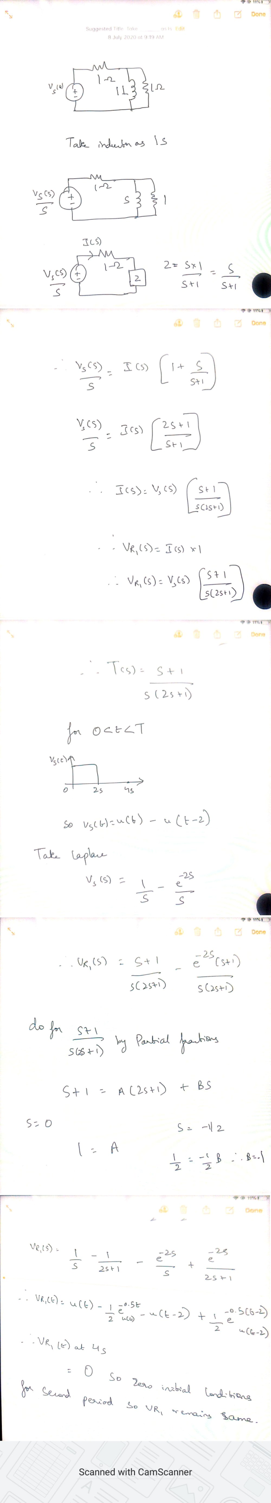
Given the following circuit shown in Fig. P2 with zero initial condition with ift) is the...
 Given the following circuit shown in Fig. P2 with zero initial condition with ift) is the input current source and vo(t) is the output voltage 193 in ? it) (1 1 не Figure P2 a) Draw the circuit in the frequency domain. b) Find the voltage Vo(s) as function of the input l(s). c) Find the transfer function: T(s)=l(s)/Vo(s).
 1) An input step voltage Vin(t)=10 u(t) Volt is applied to the circuit shown below. The initial voltage on the capacitor is zero. Using Laplace transform techniques, calculate the resulting output voltage Vout(t). R1 R2 Vout 2000 Vin c1 1000 1uF R3 1000
 Cz 개2 Ci R1 Take RL = 20 kn, R1 = R2 10 An active network is representedas shown above. (a) Use Multisim or PSpice to determine the frequency response of the network. (b) Obtain the equivalent passive network, i.e. an RLC circuit that will have the same frequency response. e2t u(t), find the output signal vo (t) of the (c) Given the input signal vs (t) passive network in (b). (d) Given the output signal vo (t) 4 sin...
 Fundamentals of Electronic Engineering
Answer should be step by step and readable (clear
handwriting)
Given: • Power voltage: • Collector resistor: • Current amplification of BJT: • Source peak voltage: • Input/Output resistance: • The corner frequency: Vcc = 12V; Rc = 4k22; B = 100; Vs = 10mV; Rvs, RL = 1 ks2; f-3dB = 100Hz. Vec=12V w • Rc www R1 HE Сс CC2 RL + R2 RE CE Find: ? Bias quiescent point: Load line, Q-point, VcEQ,...
Fundamentals of Electronic Engineering
Answer should be step by step and readable (clear
handwriting)
Given: • Power voltage: • Collector resistor: • Current amplification of BJT: • Source peak voltage: • Input/Output resistance: • The corner frequency: Vcc = 12V; Rc = 4k22; B = 100; Vs = 10mV; Rvs, RL = 1 ks2; f-3dB = 100Hz. Vec=12V w • Rc www R1 HE Сс CC2 RL + R2 RE CE Find: ? Bias quiescent point: Load line, Q-point, VcEQ,...
 As shown in the figure, a simple RL circuit (L = 1H) is powered by a 10 V batterey. The initial current in the circuit is zero. (el-0.367 -0.135, -0.049, e---0.018, e'-0.006) R t-0)0 time (sec) Vc (Volt) MW 6.33 8.65 9.51 9.82 9.94 3 4 5 6 7 8 sec.) a) Calculate the time constant of the RL circuit using the graph given above. O b) Calculate VR(t) the voltage across the resistor R. as a function of time....
 WRITE MATLAB CODE FOR IT.
Task 02: For the circuit shown in figure 12.2, the input voltage is Vi(t)-10 cos(2t) u(t) I. Plot the steady state output voltage voss(t) for t > 0 assuming zero initial conditions. I1. Determine whether the system is stable or mot? 0.5 F 2 Ohm v(t) Vo (t) 1 Ohm Figure 12.2
WRITE MATLAB CODE FOR IT.
Task 02: For the circuit shown in figure 12.2, the input voltage is Vi(t)-10 cos(2t) u(t) I. Plot the steady state output voltage voss(t) for t > 0 assuming zero initial conditions. I1. Determine whether the system is stable or mot? 0.5 F 2 Ohm v(t) Vo (t) 1 Ohm Figure 12.2
 0.5 F 20 u(t) v 1H Network for Problem 2 e. Find the s-domain current lab(s), delivered by the network to the RL load connected between terminals ab. f. Find the Transfer Function H(s) considering that the Input is the network voltage source Vs(s), and that the Output is the current lad() of item , immediately above. & Use H(s) to derive the Impulse Response h(t) of the network h. Write an expression for the Output Current lab() exclusively in...
 thx!!!!
Question 3 (5.5 marks) a) Find the transfer function of the electrical circuit shown in Figure 1. What is the value of the steady state gain(s), if any? b) If R1 1, R2 = 2n, C\ = 2- 10-3F, C 1-10-3F, calculate the time constants of the system (if any). c) Find the initial and final values of the unit impulse response of the circuit d) Derive the time-domain expression of the output if the input is the function...
thx!!!!
Question 3 (5.5 marks) a) Find the transfer function of the electrical circuit shown in Figure 1. What is the value of the steady state gain(s), if any? b) If R1 1, R2 = 2n, C\ = 2- 10-3F, C 1-10-3F, calculate the time constants of the system (if any). c) Find the initial and final values of the unit impulse response of the circuit d) Derive the time-domain expression of the output if the input is the function...
 Please find the thevenin
equivalent first as suggested
3. In the circuit below, R1 10k, R2 20k and C 0.1uF. At t0, a step function of 10 V magnitude is applied to the input. Find V(t) at the output and sketch it. Your sketch should be quantitatively correct, that is, it should have labeled V and t axes. Strongly suggested: solve by first finding the Thévenin equivalent of the source voltage and resistor network Input (problem 3) 10V IN R2...
Please find the thevenin
equivalent first as suggested
3. In the circuit below, R1 10k, R2 20k and C 0.1uF. At t0, a step function of 10 V magnitude is applied to the input. Find V(t) at the output and sketch it. Your sketch should be quantitatively correct, that is, it should have labeled V and t axes. Strongly suggested: solve by first finding the Thévenin equivalent of the source voltage and resistor network Input (problem 3) 10V IN R2...
 Given the following circuit shown in Fig. P2 with zero initial condition with ift) is the input current source and vo(t) is the output voltage 193 in ? it) (1 1 не Figure P2 a) Draw the circuit in the frequency domain. b) Find the voltage Vo(s) as function of the input l(s). c) Find the transfer function: T(s)=l(s)/Vo(s).
Most questions answered within 3 hours.
-
How do ECM Solutions assist in embedding a culture of continuous
improvement in an organization? (Project...
asked 12 minutes ago -
Directions
These directions introduce the idea of Essential Questions.
Since this may be a new concept...
asked 14 minutes ago -
1.b. Fiscal policy is said to suffer from ‘crowding out’.
Explain what this means and why...
asked 31 minutes ago -
The equation for the reaction of nitrogen and oxygen to form
nitrogen oxide is written as...
asked 36 minutes ago -
A scientist reproducing some photoelectric effect experiments
shines a light on a metal electrode, but doesn't...
asked 38 minutes ago -
In a study designed to test the effectiveness of magnets for
treating back pain, 35 patients...
asked 58 minutes ago -
Here are summary statistics for randomly selected weights of
newborn girls:
nequals=193,
x overbarxequals=30.5
hg,
sequals=7.3...
asked 48 minutes ago -
Exercise #3:
Create the “MathTest” class. It will have two class variables:
1) a question and...
asked 51 minutes ago -
In epidemiology, how do you calculate the overall incidence of
cure within two groups? What formula...
asked 55 minutes ago -
A 1 liter solution contains 0.357 M ammonium chloride and 0.268
M ammonia. Addition of 0.295...
asked 56 minutes ago -
What are the advantages and disadvantages of using virtual
reality simulations in health care education?
asked 1 hour ago -
Given input { 66, 28, 43, 29, 44, 69, 19 } and a hash function
h(x)...
asked 1 hour ago