


Homework Answers


Add Answer to:
For the six-bus system shown in Figure 2, use DC Power Flow method to find all...
For the six-bus system shown in Figure 2, use DC Power Flow method to find all...
 For the six-bus system shown in Figure 2, use DC Power Flow method to find all line flows and bus 1 (slack bus) power. Line and bus data are shown in Tables 1 and 2 respectively. The base is 100 MVA.
The six-bus system shown in Figure 1 will be simulated using MATLAB. Transmission line data and b...
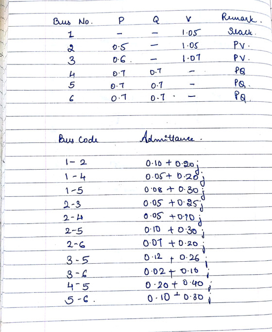
 The six-bus system shown in Figure 1 will be simulated using MATLAB. Transmission line data and bus data are given in Tables 1 and 2 respectively. The transmission line data are calculated on 100 MVA base and 230 (line-to-line) kV base for generator. Tasks: 1. Determine the network admittance matrix Y 2. Find the load flow solution using Gauss-Seidel/Newton Raphson method until first iteration by manual calculation. Use Maltab software to solve power flow problem using Gauss-Seidel method. Find the...
Consider the single line diagram of a 3-bus power system shown in Figure 2. Slack bus...
 Consider the single line diagram of a 3-bus power system shown in Figure 2. Slack bus 3 Figure 2. The data for this system are given in Tables 1 and 2. Bus Table 1 Generation Load Assumed PG QGPLQL bus voltage (MW) (MVar) (MW) (MVar) 1.05 +10.0 - - 1.0 + 0.0 50 30 305.6 140.2 1.0 +0.0 0.0 0.0 138.6 45.2 slack bus) Table 2 Bus-to-bus Impedance 0.2 + j0.04 .01 +0.03 2.3 0.0125 + j0.025 (0) Convert all...
1. In the power system network shown in Figure 1, Vi bus 1 is a slack bus with 1.00 per unit and bus 2 is a load bus wi...
 1. In the power system network shown in Figure 1, Vi bus 1 is a slack bus with 1.00 per unit and bus 2 is a load bus with S2 Mvar. The line impedance on a base of 100 MVA is Z = 0.02 + j0.04 per unit (a) Using Gauss-Seidel method, determine V2 . Use an initial estimate of V=1.0j0.0 and perform four iterations (b) If after several iterations voltage at bus 2 converges to V2 = 0.90-j0.10, determine...
The single line diagram of a power network is shown in the figure. Bus#1 is a slack bus. The sche...
 Answer part D
The single line diagram of a power network is shown in the figure. Bus#1 is a slack bus. The scheduled powers for bus#2 and bus#3 are given. The impedances shown in the figure are all in per-unit considering a power base of 100 MVA. 30 400 MW 320 MVAr Slack V-140 j0.0125 jo.0s 00 MW 270 MVAr A. Use the Gauss Seidel technique to determine voltages at bus#2 & bus#3. (Start with an initial guess 140 for...
Answer part D
The single line diagram of a power network is shown in the figure. Bus#1 is a slack bus. The scheduled powers for bus#2 and bus#3 are given. The impedances shown in the figure are all in per-unit considering a power base of 100 MVA. 30 400 MW 320 MVAr Slack V-140 j0.0125 jo.0s 00 MW 270 MVAr A. Use the Gauss Seidel technique to determine voltages at bus#2 & bus#3. (Start with an initial guess 140 for...
ystem Design December 17, 2019 2. (20 pts.) Using the "DC" power flow method find the...
 ystem Design December 17, 2019 2. (20 pts.) Using the "DC" power flow method find the real power flows in MW between the buses and the power generated in MWW by the generator on bus 1. The impedance values shown for the lines in the figure are in per unit with a base of 100 MVA and 230 kV. PG2 = 250 MW P2 = 50 MW 120 1 3 j0.25 j0.2 j0.4 P3 = 300 MW
The single line diagram of a power network is shown in the figure. Bus#1 is a slack bus. The sche...
 The single line diagram of a power network is shown in the figure. Bus#1 is a slack bus. The scheduled powers for bus#2 and bus#3 are given. The impedances shown in the figure are all in per-unit considering a power base of 100 MVA. 30 400 MW 320 MVAr Slack V-1400.0125 jo.os 3 300 MW 270 MVAr A. Use the Gauss Seidel technique to determine voltages at bus#2 & bus#3. (Start with an initial guess 140 for both buses). [Only...
2. In the two-bus system shown in Figure 59, bus l is a slack bus with...
 2. In the two-bus system shown in Figure 59, bus l is a slack bus with Vi = 1.0/0° pu. A load of 100 MW and 50 Mvar is taken from bus 2. The line impedance is zi2 0.12 + j0.16 pu on a base of 100 MVA. Using Newton-Raphson method. obtain the voltage magnitude and phase angle of bus 2. Start with an initial estimate of | ½|(0) = 1 .0 pu and δ2(0) = 0°. Perform two terations....
Q2) For the three bus power system shown below, use the NR power flow to determine the only first...
 USING NEWTON RAPHSON
Q2) For the three bus power system shown below, use the NR power flow to determine the only first iteration voltage magnitude and angle at bus 2 and bus 3. Assume that SB 100 MVA Bus 1 Bus 2 s3.85 1.90 22.36 2.0331.62 [1.89 31.62 1.89 40 W258.13 1.10 5.7/20s Gen 58.131-1.1035.772.03 31.62 1.89 35.772.03 67.231.17 250 MVr Bus Slack Bus V10510 pu Bus 3 Gen V3-1.04 pu p- 200 Mw 2 1 211 11 + i...
USING NEWTON RAPHSON
Q2) For the three bus power system shown below, use the NR power flow to determine the only first iteration voltage magnitude and angle at bus 2 and bus 3. Assume that SB 100 MVA Bus 1 Bus 2 s3.85 1.90 22.36 2.0331.62 [1.89 31.62 1.89 40 W258.13 1.10 5.7/20s Gen 58.131-1.1035.772.03 31.62 1.89 35.772.03 67.231.17 250 MVr Bus Slack Bus V10510 pu Bus 3 Gen V3-1.04 pu p- 200 Mw 2 1 211 11 + i...
(POWER SYSTEM ANALYSIS) Load + Load Figure 1. One line diagram of a three bus power...
 (POWER SYSTEM ANALYSIS) Load + Load Figure 1. One line diagram of a three bus power transmission system. In Figure 1, the power flows in the transmission lines are to be found. In this system, 100 MVA and 154 kV are the base values. The generator bus, which is shown as Bus 1, is considered to be an infinite bus and the voltage magnitude and the angle are 1 and 0°, respectively. The voltages of Bus 2 and Bus 3...
 For the six-bus system shown in Figure 2, use DC Power Flow method to find all line flows and bus 1 (slack bus) power. Line and bus data are shown in Tables 1 and 2 respectively. The base is 100 MVA.
 The six-bus system shown in Figure 1 will be simulated using MATLAB. Transmission line data and bus data are given in Tables 1 and 2 respectively. The transmission line data are calculated on 100 MVA base and 230 (line-to-line) kV base for generator. Tasks: 1. Determine the network admittance matrix Y 2. Find the load flow solution using Gauss-Seidel/Newton Raphson method until first iteration by manual calculation. Use Maltab software to solve power flow problem using Gauss-Seidel method. Find the...
 Consider the single line diagram of a 3-bus power system shown in Figure 2. Slack bus 3 Figure 2. The data for this system are given in Tables 1 and 2. Bus Table 1 Generation Load Assumed PG QGPLQL bus voltage (MW) (MVar) (MW) (MVar) 1.05 +10.0 - - 1.0 + 0.0 50 30 305.6 140.2 1.0 +0.0 0.0 0.0 138.6 45.2 slack bus) Table 2 Bus-to-bus Impedance 0.2 + j0.04 .01 +0.03 2.3 0.0125 + j0.025 (0) Convert all...
 1. In the power system network shown in Figure 1, Vi bus 1 is a slack bus with 1.00 per unit and bus 2 is a load bus with S2 Mvar. The line impedance on a base of 100 MVA is Z = 0.02 + j0.04 per unit (a) Using Gauss-Seidel method, determine V2 . Use an initial estimate of V=1.0j0.0 and perform four iterations (b) If after several iterations voltage at bus 2 converges to V2 = 0.90-j0.10, determine...
 Answer part D
The single line diagram of a power network is shown in the figure. Bus#1 is a slack bus. The scheduled powers for bus#2 and bus#3 are given. The impedances shown in the figure are all in per-unit considering a power base of 100 MVA. 30 400 MW 320 MVAr Slack V-140 j0.0125 jo.0s 00 MW 270 MVAr A. Use the Gauss Seidel technique to determine voltages at bus#2 & bus#3. (Start with an initial guess 140 for...
Answer part D
The single line diagram of a power network is shown in the figure. Bus#1 is a slack bus. The scheduled powers for bus#2 and bus#3 are given. The impedances shown in the figure are all in per-unit considering a power base of 100 MVA. 30 400 MW 320 MVAr Slack V-140 j0.0125 jo.0s 00 MW 270 MVAr A. Use the Gauss Seidel technique to determine voltages at bus#2 & bus#3. (Start with an initial guess 140 for...
 ystem Design December 17, 2019 2. (20 pts.) Using the "DC" power flow method find the real power flows in MW between the buses and the power generated in MWW by the generator on bus 1. The impedance values shown for the lines in the figure are in per unit with a base of 100 MVA and 230 kV. PG2 = 250 MW P2 = 50 MW 120 1 3 j0.25 j0.2 j0.4 P3 = 300 MW
 The single line diagram of a power network is shown in the figure. Bus#1 is a slack bus. The scheduled powers for bus#2 and bus#3 are given. The impedances shown in the figure are all in per-unit considering a power base of 100 MVA. 30 400 MW 320 MVAr Slack V-1400.0125 jo.os 3 300 MW 270 MVAr A. Use the Gauss Seidel technique to determine voltages at bus#2 & bus#3. (Start with an initial guess 140 for both buses). [Only...
 2. In the two-bus system shown in Figure 59, bus l is a slack bus with Vi = 1.0/0° pu. A load of 100 MW and 50 Mvar is taken from bus 2. The line impedance is zi2 0.12 + j0.16 pu on a base of 100 MVA. Using Newton-Raphson method. obtain the voltage magnitude and phase angle of bus 2. Start with an initial estimate of | ½|(0) = 1 .0 pu and δ2(0) = 0°. Perform two terations....
 USING NEWTON RAPHSON
Q2) For the three bus power system shown below, use the NR power flow to determine the only first iteration voltage magnitude and angle at bus 2 and bus 3. Assume that SB 100 MVA Bus 1 Bus 2 s3.85 1.90 22.36 2.0331.62 [1.89 31.62 1.89 40 W258.13 1.10 5.7/20s Gen 58.131-1.1035.772.03 31.62 1.89 35.772.03 67.231.17 250 MVr Bus Slack Bus V10510 pu Bus 3 Gen V3-1.04 pu p- 200 Mw 2 1 211 11 + i...
USING NEWTON RAPHSON
Q2) For the three bus power system shown below, use the NR power flow to determine the only first iteration voltage magnitude and angle at bus 2 and bus 3. Assume that SB 100 MVA Bus 1 Bus 2 s3.85 1.90 22.36 2.0331.62 [1.89 31.62 1.89 40 W258.13 1.10 5.7/20s Gen 58.131-1.1035.772.03 31.62 1.89 35.772.03 67.231.17 250 MVr Bus Slack Bus V10510 pu Bus 3 Gen V3-1.04 pu p- 200 Mw 2 1 211 11 + i...
 (POWER SYSTEM ANALYSIS) Load + Load Figure 1. One line diagram of a three bus power transmission system. In Figure 1, the power flows in the transmission lines are to be found. In this system, 100 MVA and 154 kV are the base values. The generator bus, which is shown as Bus 1, is considered to be an infinite bus and the voltage magnitude and the angle are 1 and 0°, respectively. The voltages of Bus 2 and Bus 3...
Most questions answered within 3 hours.
-
For the following reaction, 0.128 moles of
potassium hydrogen sulfateare mixed with
0.504 moles of potassium...
asked 3 hours ago -
1. What is the present value of $400, three years in the future
if the interest...
asked 3 hours ago -
The labor force minus the number of employed equals the number
of unemployed.
a. True
b....
asked 5 hours ago -
Determine the mass in units of grams [g] of 0.49 moles [mol]
of a new fictitious...
asked 6 hours ago -
A horizontal mass of M=5kg is on a spring and stretched to
x=0.5m when released from...
asked 7 hours ago -
26 of 50
"I have worked at the Arizona Humane Society for ten years, and
have...
asked 7 hours ago -
Compare and contrast zero based budgeting and incremental (or
base year) budgeting.
asked 7 hours ago -
4 pts 10. Which of the following hypothesis would be MOST
difficult to test experimentally? Group...
asked 7 hours ago -
A business owner makes 1,000 items a day. Each day he or she
contributes eight hours...
asked 8 hours ago -
A
circular loop in the plane of a paper lies inca0.65 T magnetic
field pointing into...
asked 8 hours ago -
A business owner is trying to decide whether to buy, rent, or
lease office space and...
asked 8 hours ago -
Thermal Storage Solar heating of a house is much more efficient
if there is a way...
asked 8 hours ago