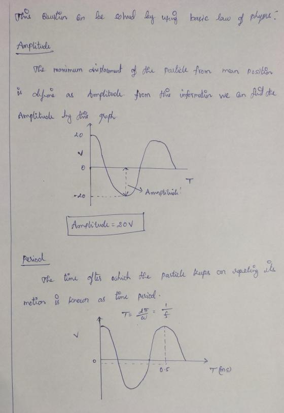
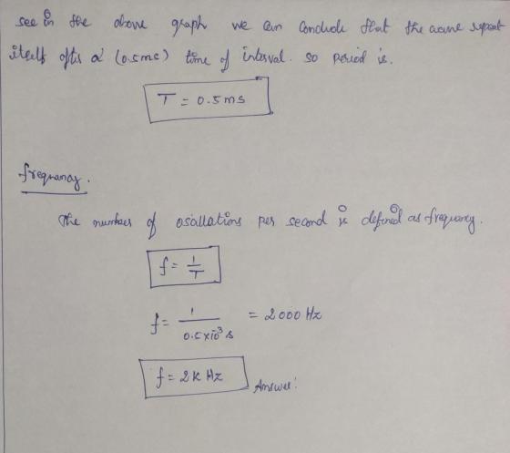
Calculate the amplitude, period and frequency of the voltage waveform shown in the graph.
The amplitude, period and frequency of the voltage waveform shown in the graph below is:

Homework Answers
this question can be solved by using basic law of physics
Add Answer to:
Calculate the amplitude, period and frequency of the voltage waveform shown in the graph.
Compute the voltage, Period, and the frequency from the images of the waveform, voltage scale and...
 Compute the voltage, Period, and the frequency from the images of the waveform, voltage scale and Time scale. VOLT/DIV MAIN TIME/DIV
If the period of a waveform is doubled, what happens to the frequency of that waveform?...
 If the period of a waveform is doubled, what happens to the frequency of that waveform? The frequency remains the same. The frequency doubles. The frequency becomes one-fourth as large. The frequency becomes four times as large. The frequency becomes half as large.
The alternating signal with an amplitude of 0.9 V, a frequency of 1 KHz, and a phase of -22.5° is o.TV dc b.as. Try connecting this signal to a load resistance of 50 Q to test the waveform 1.E...
 The alternating signal with an amplitude of 0.9 V, a frequency of 1 KHz, and a phase of -22.5° is o.TV dc b.as. Try connecting this signal to a load resistance of 50 Q to test the waveform 1.Express circuit as CAD drawing 2.Show output graph through Transient analysis in PSPICE 3.Calculate the instantaneous value at 0.1 second and compare it with the result of 2 4.When connecting the signal to the A and B terminals of the voltage distribution...
The relationship between the frequency and amplitude of the audio signal and the detected output waveform....
The relationship between the frequency and amplitude of the audio signal and the detected output waveform. The relationship between the AM envelope and the detected waveform. The causes and effects of diagonal clipping and rectifier distortion.
1. A Sinusoidal waveform of 14 V peak to peak, frequency 3.5 KHz is applied as...
 1. A Sinusoidal waveform of 14 V peak to peak, frequency 3.5 KHz is applied as an input to the circuit having Silicon diode as shown in Figure 1. Draw the approximate input and output wave forms for different V. voltages (-4V, -6Vand -8 V) and answer the interpretation questions Figure 1 Output Wave form at V=-4 V 11 Mark] volts, volts Output Wave form at V.--4 V 11 Mark] Positive peak amplitude Negative peak amplitude - Frequency = Hz...
a. For the waveform shown in figures, determine (i) Peak value (ii) the peak-to-peak voltage the...
 a. For the waveform shown in figures, determine (i) Peak value (ii) the peak-to-peak voltage the time period (iv) the frequency (v) The angular frequency. (Volls) 12V M 30 18 42 (ms) - 12V Figure 5 b. What is the frequency of the waveform shown in figure 6? m. -200 ms Figure 6 C. The figure 7 shows the variation of charge across the voltage of two capacitors namely A and B. Which of the two capacitors has higher value...
For the AM waveform s(t) shown, the carrier signal has a peak amplitude of 0.8 V...
 For the AM waveform s(t) shown, the carrier signal has a peak amplitude of 0.8 V What is the modulating index? SCO Foc 10 0.01 0.015 0.02 Pregunta 2 1 ptos. For the AM waveform s(t) shown, the carrier signal has a peak amplitude of 0.8 V What is the frequency of the message signal? Give your answer in hertz. 5x 10⁻³ 0.015 0.02 0.01
2. Given the voltage waveform in Figure. a). What is the frequency of the signal? b).What...
 2. Given the voltage waveform in Figure. a). What is the frequency of the signal? b).What is the phase shift of the waveform? c) What is the maximum amplitude of the AC signal? d). What is the sine function that describes the waveform? e). What is the cosine function that describes the waveform? * Plot of a sinusoidal signal Magnitude -15 --20 -25 0.00 0.02 0.04 0.06 0.08 0.10 0.12 0.14 Time (ms) Figure P4.1 AC Signal to be Analyzed...
The circuit to the left is constructed with a 1kS2 resistor and a 1 mF capacitor. The input waveform is shown below. A) Sketch a graph of the output voltage for this graph, starting at t 0 and en...
 The circuit to the left is constructed with a 1kS2 resistor and a 1 mF capacitor. The input waveform is shown below. A) Sketch a graph of the output voltage for this graph, starting at t 0 and ending it once the capacitor has Rreturned to an apparent steady state. Be sure to label rtant points and values ts the value of output voltage at t-11 seconds? 12 seconds? C) Sketch a graph of the output current for this graph,...
1. Determine the amplitude, period, midline, and an equation involving cosine for the graph shown in...
 1. Determine the amplitude, period, midline, and an equation involving cosine for the graph shown in the figure below. f(x) 5+ 44 3+ I -- पनि Me+
 Compute the voltage, Period, and the frequency from the images of the waveform, voltage scale and Time scale. VOLT/DIV MAIN TIME/DIV
 If the period of a waveform is doubled, what happens to the frequency of that waveform? The frequency remains the same. The frequency doubles. The frequency becomes one-fourth as large. The frequency becomes four times as large. The frequency becomes half as large.
 The alternating signal with an amplitude of 0.9 V, a frequency of 1 KHz, and a phase of -22.5° is o.TV dc b.as. Try connecting this signal to a load resistance of 50 Q to test the waveform 1.Express circuit as CAD drawing 2.Show output graph through Transient analysis in PSPICE 3.Calculate the instantaneous value at 0.1 second and compare it with the result of 2 4.When connecting the signal to the A and B terminals of the voltage distribution...
 1. A Sinusoidal waveform of 14 V peak to peak, frequency 3.5 KHz is applied as an input to the circuit having Silicon diode as shown in Figure 1. Draw the approximate input and output wave forms for different V. voltages (-4V, -6Vand -8 V) and answer the interpretation questions Figure 1 Output Wave form at V=-4 V 11 Mark] volts, volts Output Wave form at V.--4 V 11 Mark] Positive peak amplitude Negative peak amplitude - Frequency = Hz...
 a. For the waveform shown in figures, determine (i) Peak value (ii) the peak-to-peak voltage the time period (iv) the frequency (v) The angular frequency. (Volls) 12V M 30 18 42 (ms) - 12V Figure 5 b. What is the frequency of the waveform shown in figure 6? m. -200 ms Figure 6 C. The figure 7 shows the variation of charge across the voltage of two capacitors namely A and B. Which of the two capacitors has higher value...
 For the AM waveform s(t) shown, the carrier signal has a peak amplitude of 0.8 V What is the modulating index? SCO Foc 10 0.01 0.015 0.02 Pregunta 2 1 ptos. For the AM waveform s(t) shown, the carrier signal has a peak amplitude of 0.8 V What is the frequency of the message signal? Give your answer in hertz. 5x 10⁻³ 0.015 0.02 0.01
 2. Given the voltage waveform in Figure. a). What is the frequency of the signal? b).What is the phase shift of the waveform? c) What is the maximum amplitude of the AC signal? d). What is the sine function that describes the waveform? e). What is the cosine function that describes the waveform? * Plot of a sinusoidal signal Magnitude -15 --20 -25 0.00 0.02 0.04 0.06 0.08 0.10 0.12 0.14 Time (ms) Figure P4.1 AC Signal to be Analyzed...
 The circuit to the left is constructed with a 1kS2 resistor and a 1 mF capacitor. The input waveform is shown below. A) Sketch a graph of the output voltage for this graph, starting at t 0 and ending it once the capacitor has Rreturned to an apparent steady state. Be sure to label rtant points and values ts the value of output voltage at t-11 seconds? 12 seconds? C) Sketch a graph of the output current for this graph,...
 1. Determine the amplitude, period, midline, and an equation involving cosine for the graph shown in the figure below. f(x) 5+ 44 3+ I -- पनि Me+
Most questions answered within 3 hours.
-
What is the path of a carbon atom during photosynthesis , light
dependent and non dependent,...
asked 1 minute from now -
The balanced equation for the combustion of butane,
C4H10, is
2 C4H10(g) + 13
O2(g) →...
asked 1 minute from now -
Q1 At depths of 2000 m in the sea, the pressure is about 200
times atmospheric...
asked 14 minutes ago -
A value commonly taken for the perception reaction time of
motorists is delta t equals 1.5...
asked 6 minutes ago -
For
a test of independent groups, a t test can still be conducted even
when assumptions...
asked 27 minutes ago -
What assumption are we making about ratings e.g., that ratings
are important in motivating poor performers...
asked 34 minutes ago -
You’ve observed the following returns on Crash-n-Burn Computer’s
stock over the past five years: 11 percent,...
asked 36 minutes ago -
In which of the following cases is the displacement's
magnitude half the distance traveled? a. 10...
asked 57 minutes ago -
(InputMismatchException) and (ArrayIndexOutOfBoundsException):
Using the two arrays shown below, write a program that prompts the
user...
asked 52 minutes ago -
A basketball of mass m = 630 g rolls off the hoop's rim, falls
from a...
asked 1 hour ago -
What is the activity [A] of Na+ in a .05M solution of NaCl at
25C? You...
asked 1 hour ago -
You own a bond portfolio worth $41,000. You estimate that your
portfolio has an average YTM...
asked 1 hour ago