
Homework Answers

Add Answer to:
The circuit to the left is constructed with a 1kS2 resistor and a 1 mF capacitor. The input waveform is shown below. A) Sketch a graph of the output voltage for this graph, starting at t 0 and en...
Challenge Problem... The circuit to the left is constructed with a 1k2 resistor and a 1 mF capacitor. The input wavefor...
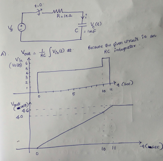
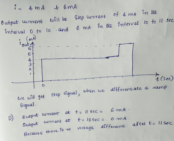
 Challenge Problem... The circuit to the left is constructed with a 1k2 resistor and a 1 mF capacitor. The input waveform is shown below. i(t) in 2 V, (t) o2 13 A) Sketch a graph of the output voltage for this graph, starting att 0 and ending it once the RESISTOR has returned to an apparent steady state. Be sure to label important points and values. B) What is the value of output voltage at t 11 seconds? 12 seconds?...
PART B: 04 Sketch graph for sin waveform and cosine waveform for AC voltage and AC...
 PART B: 04 Sketch graph for sin waveform and cosine waveform for AC voltage and AC current. (4 marks) (b) Obtain the energy stored in each capacitor in Figure Q4(b) under DC conditions. (6 marks) (c) Determine the current through a 200 uF capacitor whose voltage is shown in Figure Q4(c). Sketch graph for current, I versus time, t. (10 marks) 2 mF Η Λ 2 ΚΩ 5 ΚΩ ΛΜ 6 mA 3 ΚΩ ΑΛΛ 4 ΚΩ 4 mE Figure...
For the MOS transistor circuit below, the capacitor is discharged in the beginning. 0.2V, β = 0.2mA/V2, and C = 1mF. VDD-1V, VTH For the clock voltage shown, plot the voltage waveform vc(t) and label...
 For the MOS transistor circuit below, the capacitor is
discharged in the beginning.
0.2V, β = 0.2mA/V2, and C = 1mF. VDD-1V, VTH For the clock voltage shown, plot the voltage waveform vc(t) and label its steady state values. CLK м, VDD
0.2V, β = 0.2mA/V2, and C = 1mF. VDD-1V, VTH For the clock voltage shown, plot the voltage waveform vc(t) and label its steady state values. CLK м, VDD
For the MOS transistor circuit below, the capacitor is
discharged in the beginning.
0.2V, β = 0.2mA/V2, and C = 1mF. VDD-1V, VTH For the clock voltage shown, plot the voltage waveform vc(t) and label its steady state values. CLK м, VDD
0.2V, β = 0.2mA/V2, and C = 1mF. VDD-1V, VTH For the clock voltage shown, plot the voltage waveform vc(t) and label its steady state values. CLK м, VDD
Answer please 7. The voltage across a 2 mF capacitor is shown below capacitor (clearly state...
 Answer please
7. The voltage across a 2 mF capacitor is shown below capacitor (clearly state the value as a function o waveform. (15 points) Determine the current raw the resulting curre 10 4 (uS)
Answer please
7. The voltage across a 2 mF capacitor is shown below capacitor (clearly state the value as a function o waveform. (15 points) Determine the current raw the resulting curre 10 4 (uS)
24) For the three circuits (a), (b) and (c) shown below, the waveform of input voltage...
 24) For the three circuits (a), (b) and (c) shown below, the waveform of input voltage vy is given as shown below. For each circuit, sketch the waveform of output voltage vo for the given input voltage . Label the most positive and most negative output levels. Assume all diodes are ideal (vp- 0) and CR>> T. (10 points) +10 V-- -10 V TI ms (3 points) (b) o- (3 points) 3V (4 points) DH
A triangular waveform voltage (shown below to the right) is applied to the following circuit input...
 A triangular waveform voltage (shown below to the right) is
applied to the following circuit input terminals. The circuit’s
value of C is 200 nano-farad and the value of R is 47 kilo-ohm. The
output voltage is measured with a high impedance A-to-D converter.
Recalling that such a passive element circuit is a linear-time
invariant system which can be solved with superposition
principles:
a) Determine eout at time = 1.5 milli-second.
b) Determine the time when there is no current...
A triangular waveform voltage (shown below to the right) is
applied to the following circuit input terminals. The circuit’s
value of C is 200 nano-farad and the value of R is 47 kilo-ohm. The
output voltage is measured with a high impedance A-to-D converter.
Recalling that such a passive element circuit is a linear-time
invariant system which can be solved with superposition
principles:
a) Determine eout at time = 1.5 milli-second.
b) Determine the time when there is no current...
A circuit is constructed with an AC generator, a resistor, capacitor and inductor as shown. The...
 A circuit is constructed with an AC generator,
a resistor, capacitor and inductor as shown. The generator voltage
varies in time as ? =Va - Vb =
?msin?t, where
?m = 120 V and ? =
221 radians/second. The inductance L = 352 mH. The values for the
capacitance C and the resistance R are unkown. What is known is
that the current in the circuit leads the voltage across the
generator by ? = 58 degrees and the average...
A circuit is constructed with an AC generator,
a resistor, capacitor and inductor as shown. The generator voltage
varies in time as ? =Va - Vb =
?msin?t, where
?m = 120 V and ? =
221 radians/second. The inductance L = 352 mH. The values for the
capacitance C and the resistance R are unkown. What is known is
that the current in the circuit leads the voltage across the
generator by ? = 58 degrees and the average...
nde) Figare 18 Circuit for Problem 15 Analysis 1. Plot the input and output vollage wavefoems nlt) and lt) as wel as the capacitor current iclt) for the input wavelorm shown in Fig ure 1....
 nde) Figare 18 Circuit for Problem 15 Analysis 1. Plot the input and output vollage wavefoems nlt) and lt) as wel as the capacitor current iclt) for the input wavelorm shown in Fig ure 1.10 on the next page, Assume the capacitoris initially discharged 2 Determine the following numerical descriptors for lf) and iclf (a) Voltage values of t) at times-250, 650, and 960ms. (b) Peak capacitor current t Discass the relationship between the plots of the capacitor current ic(t)...
1. Consider the single-phase VSI inverter shown below dc VR(t) iz(t) a) If your input voltage Vdc...
 1. Consider the single-phase VSI inverter shown below dc VR(t) iz(t) a) If your input voltage Vdc - 100V2 V and switching frequency is 60 Hz with zero delay angle. Then, sketch the square wave output. Mark the peak values [10 marks] b) Sketch the fundamental output on the top of the above waveform. Mark the peak value По marksl c) The above A VSI is used to create a square wave output with 100v2 V at 60 Hz. This...
Question 1. (a) Consider the waveform below that has a period of T of 0.04 seconds....
 Question 1. (a) Consider the waveform below that has a period of T of 0.04 seconds. What is the rms voltage of this waveform? V(t) 15 V 0.01 s 0.02 s T=0.04s (b) The figure below shows a network of resistances and reactances having values as shown connected to a voltage source with a voltage of (50+0j) volts rms and an angular frequency of 1000 rad/s. А. 32 3 mH V 52 200 uF 2 mH 1 mH (i) Redraw...
 Challenge Problem... The circuit to the left is constructed with a 1k2 resistor and a 1 mF capacitor. The input waveform is shown below. i(t) in 2 V, (t) o2 13 A) Sketch a graph of the output voltage for this graph, starting att 0 and ending it once the RESISTOR has returned to an apparent steady state. Be sure to label important points and values. B) What is the value of output voltage at t 11 seconds? 12 seconds?...
 PART B: 04 Sketch graph for sin waveform and cosine waveform for AC voltage and AC current. (4 marks) (b) Obtain the energy stored in each capacitor in Figure Q4(b) under DC conditions. (6 marks) (c) Determine the current through a 200 uF capacitor whose voltage is shown in Figure Q4(c). Sketch graph for current, I versus time, t. (10 marks) 2 mF Η Λ 2 ΚΩ 5 ΚΩ ΛΜ 6 mA 3 ΚΩ ΑΛΛ 4 ΚΩ 4 mE Figure...
 For the MOS transistor circuit below, the capacitor is
discharged in the beginning.
0.2V, β = 0.2mA/V2, and C = 1mF. VDD-1V, VTH For the clock voltage shown, plot the voltage waveform vc(t) and label its steady state values. CLK м, VDD
0.2V, β = 0.2mA/V2, and C = 1mF. VDD-1V, VTH For the clock voltage shown, plot the voltage waveform vc(t) and label its steady state values. CLK м, VDD
For the MOS transistor circuit below, the capacitor is
discharged in the beginning.
0.2V, β = 0.2mA/V2, and C = 1mF. VDD-1V, VTH For the clock voltage shown, plot the voltage waveform vc(t) and label its steady state values. CLK м, VDD
0.2V, β = 0.2mA/V2, and C = 1mF. VDD-1V, VTH For the clock voltage shown, plot the voltage waveform vc(t) and label its steady state values. CLK м, VDD
 Answer please
7. The voltage across a 2 mF capacitor is shown below capacitor (clearly state the value as a function o waveform. (15 points) Determine the current raw the resulting curre 10 4 (uS)
Answer please
7. The voltage across a 2 mF capacitor is shown below capacitor (clearly state the value as a function o waveform. (15 points) Determine the current raw the resulting curre 10 4 (uS)
 24) For the three circuits (a), (b) and (c) shown below, the waveform of input voltage vy is given as shown below. For each circuit, sketch the waveform of output voltage vo for the given input voltage . Label the most positive and most negative output levels. Assume all diodes are ideal (vp- 0) and CR>> T. (10 points) +10 V-- -10 V TI ms (3 points) (b) o- (3 points) 3V (4 points) DH
 A triangular waveform voltage (shown below to the right) is
applied to the following circuit input terminals. The circuit’s
value of C is 200 nano-farad and the value of R is 47 kilo-ohm. The
output voltage is measured with a high impedance A-to-D converter.
Recalling that such a passive element circuit is a linear-time
invariant system which can be solved with superposition
principles:
a) Determine eout at time = 1.5 milli-second.
b) Determine the time when there is no current...
A triangular waveform voltage (shown below to the right) is
applied to the following circuit input terminals. The circuit’s
value of C is 200 nano-farad and the value of R is 47 kilo-ohm. The
output voltage is measured with a high impedance A-to-D converter.
Recalling that such a passive element circuit is a linear-time
invariant system which can be solved with superposition
principles:
a) Determine eout at time = 1.5 milli-second.
b) Determine the time when there is no current...
 A circuit is constructed with an AC generator,
a resistor, capacitor and inductor as shown. The generator voltage
varies in time as ? =Va - Vb =
?msin?t, where
?m = 120 V and ? =
221 radians/second. The inductance L = 352 mH. The values for the
capacitance C and the resistance R are unkown. What is known is
that the current in the circuit leads the voltage across the
generator by ? = 58 degrees and the average...
A circuit is constructed with an AC generator,
a resistor, capacitor and inductor as shown. The generator voltage
varies in time as ? =Va - Vb =
?msin?t, where
?m = 120 V and ? =
221 radians/second. The inductance L = 352 mH. The values for the
capacitance C and the resistance R are unkown. What is known is
that the current in the circuit leads the voltage across the
generator by ? = 58 degrees and the average...
 nde) Figare 18 Circuit for Problem 15 Analysis 1. Plot the input and output vollage wavefoems nlt) and lt) as wel as the capacitor current iclt) for the input wavelorm shown in Fig ure 1.10 on the next page, Assume the capacitoris initially discharged 2 Determine the following numerical descriptors for lf) and iclf (a) Voltage values of t) at times-250, 650, and 960ms. (b) Peak capacitor current t Discass the relationship between the plots of the capacitor current ic(t)...
 1. Consider the single-phase VSI inverter shown below dc VR(t) iz(t) a) If your input voltage Vdc - 100V2 V and switching frequency is 60 Hz with zero delay angle. Then, sketch the square wave output. Mark the peak values [10 marks] b) Sketch the fundamental output on the top of the above waveform. Mark the peak value По marksl c) The above A VSI is used to create a square wave output with 100v2 V at 60 Hz. This...
 Question 1. (a) Consider the waveform below that has a period of T of 0.04 seconds. What is the rms voltage of this waveform? V(t) 15 V 0.01 s 0.02 s T=0.04s (b) The figure below shows a network of resistances and reactances having values as shown connected to a voltage source with a voltage of (50+0j) volts rms and an angular frequency of 1000 rad/s. А. 32 3 mH V 52 200 uF 2 mH 1 mH (i) Redraw...
Most questions answered within 3 hours.
-
Little’s Law: Val d’Costa is a world famous ski village in the
French Alps. Because of...
asked 4 minutes ago -
Find the absolute error D for the calculation if A + B/C=D A=
9.4 +/- 0.4...
asked 17 minutes ago -
New Air Heating and Cooling, manufactures furnaces and central
air units. The company pride itself on...
asked 31 minutes ago -
A coach uses a new technique to train gymnasts. Seven
gymnasts were randomly selected and their...
asked 2 hours ago -
While rotating the tires on your car you notice a rock [mass =
0.1 Kg] stuck...
asked 4 hours ago -
Using MARS simulator, write MIPS programs according to
the following scenarios: Receive a positive integer number...
asked 6 hours ago -
An object in front of a concave mirror has a real image that is
11.5 cm...
asked 6 hours ago -
Consider the reaction, C3 H8 + O2 --> CO2 + H2O. How many
moles of O2...
asked 8 hours ago -
You and your opponent both roll a fair die. If you both roll the
same number,...
asked 8 hours ago -
In a study of the accuracy of fast food drive-through orders,
Restaurant A had 257 accurate...
asked 8 hours ago -
Identify and describe in detail the four categories of
institutions that could be included in a...
asked 8 hours ago -
In python
class Customer:
def __init__(self, customer_id, last_name, first_name, phone_number, address):
self._customer_id = int(customer_id)
self._last_name =...
asked 8 hours ago