
![Vi t [s] 0.5 1.0 Figure 1.10 nput waveform for Problem 1.9 on the preceding page Simulation with NI Multisim Enter the circui](http://img.homeworklib.com/images/d4a315d5-7ec2-4a63-974d-42b48e3c414d.png?x-oss-process=image/resize,w_560)


Vi t [s] 0.5 1.0 Figure 1.10 nput waveform for Problem 1.9 on the preceding page Simulation with NI Multisim Enter the circuit of Figure 1.9 on the preceding page using the 1N4148 diode model. Use the PIECEWISE LINEAR VOLTAGE source to create the nput waveform pictured in Figure L.10. 1. Set up a Simulabe Analyses -Transient analysis to plot the input and output voltage waveforms n(r) and e(f) 2. Set up a second transient analysis to plot the input veltage waveform and the capacitor carrent ic(f) use a second axis on the right side of the plot for current 3. Determine the following numerical descriptors for elt) and icltf (a) Voltage values of lf) at timest 250, 650, and 950 ms. (b) Peak capacitor current Additional Multisim tips for this problem: . Set distinct colors for the waveform traces to easily distinguish the input and output waveforms .9. PEAK RECTIFIER 45 e Refer to the tutorial videos below to learn how to take cursor mea surements Erom the oscilloscope. NI Multisim video tutorials .Piecewise linear (PWL) voltage source with Transient Analysis . Plot time-doenain circuit response pa//yout u.be/waknad EXk . Plot second variable on its own axis in Grapher View
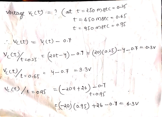
Figure 1.9 shows a peak rectifier, also known as a peak detector, a circuit whose output tracks the most-recent maximum value of the input signal. vi(t) Figure 1.9: Circuit for Problem 1.9 Analysis 1. Plot the input and output voltage waveforms v(t) and vo(t) as well as the capacitor current ic(t) for the input waveform shown in Fig ure 1.10 on the next page, Assume the capacitor is initially discharged. 2. Determine the following numerical descriptors foro(t) and ic(t): (a) Voltage values of vo(t) at times t-250, 650, and 950 ms. (b) Peak capacitor current. 3. Discuss the relationship between the plots of the capacitor current ic(t) and the output voltage vo(t). Use the following circuit components: Component Value -D 0.7 volt forward-biased voltage drop, ideal diode otherwise 1.011F
Simulation with NI Multisim Enter the circuit of Figure 1.9 on the preceding page using the 1N4148 diode model. Use the PIECEWISE LINEAR VOLTAGE source to create the input waveform pictured in Figure 1.10 1. Set up a Simulate Analyses -Transient analysis to plot the input and output voltage waveforms vi(t) and vo(t). 2. Set up a second transient analysis to plot the input voltage waveform and the capacitor current ic(t); use a second axis on the right side of the plot for current. 3. Determine the following numerical descriptors for vo(t) and ic(t): (a) Voltage values of vo(t) at times t -250, 650, and 950 ms. (b) Peak capacitor current. Additional Multisim tips for this problem: .Set distinct colors for the waveform traces to easily distinguish the input and output waveforms.
Homework Answers


Add Answer to:
nde) Figare 18 Circuit for Problem 15 Analysis 1. Plot the input and output vollage wavefoems nlt) and lt) as wel as the capacitor current iclt) for the input wavelorm shown in Fig ure 1....
02 +Vo D3 Rgare 18 Circuit for Problem 1 Analysis 1. Copy the circuit of Figure 1.8 and sketch the ow of pesitive curment throughout the entire circuit for o>0. Repeat for n ce 2....
 02 +Vo D3 Rgare 18 Circuit for Problem 1 Analysis 1. Copy the circuit of Figure 1.8 and sketch the ow of pesitive curment throughout the entire circuit for o>0. Repeat for n ce 2. Plot two periods of nlt) and s) for each of the thee input wave shown in Figune 17 on page 37 fom output t (a) Feak value, and b) Eflective DC value, also known as RMS value NotTE These and are therefore optional 4. Determine...
done on pspice thank you Part IV: Diode Rectifiers Procedure: 1. Build the circuit model for...
 done on pspice thank you
Part IV: Diode Rectifiers Procedure: 1. Build the circuit model for full-wave diode rectifier in PSpice as shown in Fig. 4. The value of the load resistor is 10 k22. The input AC voltage source (VSIN in PSpice) is configured at 100 Hz and 20 V (peak-to- peak) in sinusoidal waveform. O 10K V.(t) V(A) A Figure 4. Circuit configuration for full-wave diode rectifier 2. Run the simulation and save the input and output voltage...
done on pspice thank you
Part IV: Diode Rectifiers Procedure: 1. Build the circuit model for full-wave diode rectifier in PSpice as shown in Fig. 4. The value of the load resistor is 10 k22. The input AC voltage source (VSIN in PSpice) is configured at 100 Hz and 20 V (peak-to- peak) in sinusoidal waveform. O 10K V.(t) V(A) A Figure 4. Circuit configuration for full-wave diode rectifier 2. Run the simulation and save the input and output voltage...
Figure 1(a) and 1(b) show the input and output voltage of a clamper circuit with assumption of an ideal diode.
 Figure 1(a) and 1(b) show the input and output voltage of a clamper circuit with assumption of an ideal diode. a. Design a clamper circuit that will produce the output waveform as shown in Figure 1(b).b. Prove the value of output voltage, Vo for positive cycle and negative cycle of input by calculation. c. Repeat step 1b by assuming the diode is germanium type and sketch the new output waveform produced by the clamper circuit.
Q.1. (a) For the following clipper circuit, plot the output versus time. The diode in the...
 Q.1. (a) For the following clipper circuit, plot the output versus time. The diode in the circuit has piecewise linear parameters Vs = 0.7 V and 1= 10 (10) R=1002 w DI VO 30 V + 10 V -30 vf (b) Sketch the output voltage V, versus time for the following circuit with the input voltage shown. Assume V = 0 and assume the RC time constant is large. (15) VA -H VO 20 V с Vg=5V = -20 V
please help Question 1 Consider the following circuit, where the reverse saturation current (Is) is the...
 please help
Question 1 Consider the following circuit, where the reverse saturation current (Is) is the same for each diode. D2 o Vo Di Vi WWW R 32 23 a. b. Determine an algebraic expression for V1, for a given Vo, and Is. Given an Is of 40 FA and R1 = 3.3 kl , determine the Vi that produces an output voltage (V.) of 0.625 V. C. Recalculate question-b if Is were to be a thousand times greater at...
please help
Question 1 Consider the following circuit, where the reverse saturation current (Is) is the same for each diode. D2 o Vo Di Vi WWW R 32 23 a. b. Determine an algebraic expression for V1, for a given Vo, and Is. Given an Is of 40 FA and R1 = 3.3 kl , determine the Vi that produces an output voltage (V.) of 0.625 V. C. Recalculate question-b if Is were to be a thousand times greater at...
The circuit to the left is constructed with a 1kS2 resistor and a 1 mF capacitor. The input waveform is shown below. A) Sketch a graph of the output voltage for this graph, starting at t 0 and en...
 The circuit to the left is constructed with a 1kS2 resistor and a 1 mF capacitor. The input waveform is shown below. A) Sketch a graph of the output voltage for this graph, starting at t 0 and ending it once the capacitor has Rreturned to an apparent steady state. Be sure to label rtant points and values ts the value of output voltage at t-11 seconds? 12 seconds? C) Sketch a graph of the output current for this graph,...
(5) Capacitor and Transient Analysis 7 marks Fig. P-5A shows a switching circuit with switches Si...
 (5) Capacitor and Transient Analysis 7 marks Fig. P-5A shows a switching circuit with switches Si and S2 that are opened and closed periodically. Fig. P-5B shows the steady state waveform of the output voltage V.(t). Compute the steady state values of V1 and V2. R: Vo(t) Vo(t) Vot 5V V2 --- -- 1kΩ 1uF C Vi Ve 5V Fig. P-5A Fig. P-5B (not to scale) (5a) 3 marks Let the initial voltage of the capacitor be V.(O)= V1. The...
QUESTION 5 (15 points) a. You have a power supply which is a full-wave rectifier with a capacitor filter. It operates f...
 QUESTION 5 (15 points) a. You have a power supply which is a full-wave rectifier with a capacitor filter. It operates from the mains and provides an output of Voc-20 V with 20% ripple, when the load current is 2 A Calculate the maximum and minimum values of the output waveform of this power supply. b. Now you will design a series voltage regulator between the power supply described in part (a) and an electronic device operating at 12 VDC...
1. Use MultiSim program to simulate the RC circuit shown in Figures 1 using nominal resistor valu...
 1. Use MultiSim program to simulate the RC circuit shown in Figures 1 using nominal resistor value of 100Ω and 10uF capacitor. Set up the function generator for: square wave, frequency 20Hz, duty cycle 50%, offset 1V, and amplitude 1V. Use Tektronix scope to display the input source and the capacitor voltage waveforms on the same display 2. Print out your schematics and print an output showing Channels A and B 3. Use the scope cursors to measure simulated t...
Challenge Problem... The circuit to the left is constructed with a 1k2 resistor and a 1 mF capacitor. The input wavefor...
 Challenge Problem... The circuit to the left is constructed with a 1k2 resistor and a 1 mF capacitor. The input waveform is shown below. i(t) in 2 V, (t) o2 13 A) Sketch a graph of the output voltage for this graph, starting att 0 and ending it once the RESISTOR has returned to an apparent steady state. Be sure to label important points and values. B) What is the value of output voltage at t 11 seconds? 12 seconds?...
 02 +Vo D3 Rgare 18 Circuit for Problem 1 Analysis 1. Copy the circuit of Figure 1.8 and sketch the ow of pesitive curment throughout the entire circuit for o>0. Repeat for n ce 2. Plot two periods of nlt) and s) for each of the thee input wave shown in Figune 17 on page 37 fom output t (a) Feak value, and b) Eflective DC value, also known as RMS value NotTE These and are therefore optional 4. Determine...
 done on pspice thank you
Part IV: Diode Rectifiers Procedure: 1. Build the circuit model for full-wave diode rectifier in PSpice as shown in Fig. 4. The value of the load resistor is 10 k22. The input AC voltage source (VSIN in PSpice) is configured at 100 Hz and 20 V (peak-to- peak) in sinusoidal waveform. O 10K V.(t) V(A) A Figure 4. Circuit configuration for full-wave diode rectifier 2. Run the simulation and save the input and output voltage...
done on pspice thank you
Part IV: Diode Rectifiers Procedure: 1. Build the circuit model for full-wave diode rectifier in PSpice as shown in Fig. 4. The value of the load resistor is 10 k22. The input AC voltage source (VSIN in PSpice) is configured at 100 Hz and 20 V (peak-to- peak) in sinusoidal waveform. O 10K V.(t) V(A) A Figure 4. Circuit configuration for full-wave diode rectifier 2. Run the simulation and save the input and output voltage...
 Q.1. (a) For the following clipper circuit, plot the output versus time. The diode in the circuit has piecewise linear parameters Vs = 0.7 V and 1= 10 (10) R=1002 w DI VO 30 V + 10 V -30 vf (b) Sketch the output voltage V, versus time for the following circuit with the input voltage shown. Assume V = 0 and assume the RC time constant is large. (15) VA -H VO 20 V с Vg=5V = -20 V
 please help
Question 1 Consider the following circuit, where the reverse saturation current (Is) is the same for each diode. D2 o Vo Di Vi WWW R 32 23 a. b. Determine an algebraic expression for V1, for a given Vo, and Is. Given an Is of 40 FA and R1 = 3.3 kl , determine the Vi that produces an output voltage (V.) of 0.625 V. C. Recalculate question-b if Is were to be a thousand times greater at...
please help
Question 1 Consider the following circuit, where the reverse saturation current (Is) is the same for each diode. D2 o Vo Di Vi WWW R 32 23 a. b. Determine an algebraic expression for V1, for a given Vo, and Is. Given an Is of 40 FA and R1 = 3.3 kl , determine the Vi that produces an output voltage (V.) of 0.625 V. C. Recalculate question-b if Is were to be a thousand times greater at...
 The circuit to the left is constructed with a 1kS2 resistor and a 1 mF capacitor. The input waveform is shown below. A) Sketch a graph of the output voltage for this graph, starting at t 0 and ending it once the capacitor has Rreturned to an apparent steady state. Be sure to label rtant points and values ts the value of output voltage at t-11 seconds? 12 seconds? C) Sketch a graph of the output current for this graph,...
 (5) Capacitor and Transient Analysis 7 marks Fig. P-5A shows a switching circuit with switches Si and S2 that are opened and closed periodically. Fig. P-5B shows the steady state waveform of the output voltage V.(t). Compute the steady state values of V1 and V2. R: Vo(t) Vo(t) Vot 5V V2 --- -- 1kΩ 1uF C Vi Ve 5V Fig. P-5A Fig. P-5B (not to scale) (5a) 3 marks Let the initial voltage of the capacitor be V.(O)= V1. The...
 QUESTION 5 (15 points) a. You have a power supply which is a full-wave rectifier with a capacitor filter. It operates from the mains and provides an output of Voc-20 V with 20% ripple, when the load current is 2 A Calculate the maximum and minimum values of the output waveform of this power supply. b. Now you will design a series voltage regulator between the power supply described in part (a) and an electronic device operating at 12 VDC...
 1. Use MultiSim program to simulate the RC circuit shown in Figures 1 using nominal resistor value of 100Ω and 10uF capacitor. Set up the function generator for: square wave, frequency 20Hz, duty cycle 50%, offset 1V, and amplitude 1V. Use Tektronix scope to display the input source and the capacitor voltage waveforms on the same display 2. Print out your schematics and print an output showing Channels A and B 3. Use the scope cursors to measure simulated t...
 Challenge Problem... The circuit to the left is constructed with a 1k2 resistor and a 1 mF capacitor. The input waveform is shown below. i(t) in 2 V, (t) o2 13 A) Sketch a graph of the output voltage for this graph, starting att 0 and ending it once the RESISTOR has returned to an apparent steady state. Be sure to label important points and values. B) What is the value of output voltage at t 11 seconds? 12 seconds?...
Most questions answered within 3 hours.
-
Accent Software faces the following conditions. All of these
support Accent’s use of a market-penetration pricing...
asked 54 minutes ago -
A mathematically inclined friend emails you the following
instructions: "Meet me in the cafeteria the first...
asked 57 minutes ago -
A monopoly sells in two countries . The demand curves in the two
countries are p1...
asked 1 hour ago -
A .15kg rubber ball is bounced off a wall. Before hitting the
wall, the ball moves...
asked 2 hours ago -
A manufacturing company preparing to build a new plant is
considering three potential locations for it....
asked 2 hours ago -
B. If compound Y has approximately the same values of solubility
in toluene as compound X,...
asked 3 hours ago -
Oscar Inc. has inventory in Japan valued at 39,051,000 Yen one
year ago. One year ago...
asked 3 hours ago -
If Canada suffered from "fundamental disequilibrium," and its
government choose not to devalue its currency, a...
asked 3 hours ago -
4. How many input & output Key Value Pairs are passed into,
and emitted out of...
asked 3 hours ago -
Why would your heart not function well if constructed of
skeletal muscle? What is the particular...
asked 3 hours ago -
Please respond to this essay question in full essay form for
Chemistry 1102 Organic and Biochemistry:...
asked 3 hours ago -
Determine the head loss and velocity of flow in a water supply main
of 15.0 cm...
asked 3 hours ago