


Homework Answers

![for Vor 0.650 0654 ERIL R 3 9-300.65 m 50 Rje & [ 9. 19 -1.9553 2.6 *] 061 R Rj. 26.844 kr for Voro.lv 9-380.7 (9-2.1) X3 4x0](http://img.homeworklib.com/questions/62f08460-0b2b-11eb-8dba-ed8643d432b9.png?x-oss-process=image/resize,w_560)
Add Answer to:
please help
Question 1 Consider the following circuit, where the reverse saturation current (Is) is the...
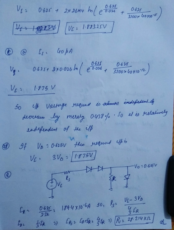
Q4. Most electronic systems need a dc voltage to work properly. The AC-to-DC power supply system ...
 part g
Q4. Most electronic systems need a dc voltage to work properly. The AC-to-DC power supply system is including a transformer, a rectifier and a capacitor input filter. The AC input voltage is 110 Vrms at 60 Hz. (a) Draw the full wave bridge rectifier circuit with transformer which steps down voltage to safer and lower levels that are more suitable for use with diodes (b) Show how the capacitor input filter connects to the rectifier output in the...
part g
Q4. Most electronic systems need a dc voltage to work properly. The AC-to-DC power supply system is including a transformer, a rectifier and a capacitor input filter. The AC input voltage is 110 Vrms at 60 Hz. (a) Draw the full wave bridge rectifier circuit with transformer which steps down voltage to safer and lower levels that are more suitable for use with diodes (b) Show how the capacitor input filter connects to the rectifier output in the...
i want the answer with detales Single-Phase Controlled Rectifier Exercise Derive the expressions of the average...
 i want the answer with detales
Single-Phase Controlled Rectifier Exercise Derive the expressions of the average load voltage and current in single-phase half-wave controlled rectifiers and resistive load. Draw the waveforms of supply voltage. output voltage, output current, thyristor voltage and thyristor current Exercise In a single-phase half-wave controlled rectifier and resistive kad, it is desired to get an average load voltage of 80 V. Determine the firing angle if the ac supply voltage is 230 V. If the load...
i want the answer with detales
Single-Phase Controlled Rectifier Exercise Derive the expressions of the average load voltage and current in single-phase half-wave controlled rectifiers and resistive load. Draw the waveforms of supply voltage. output voltage, output current, thyristor voltage and thyristor current Exercise In a single-phase half-wave controlled rectifier and resistive kad, it is desired to get an average load voltage of 80 V. Determine the firing angle if the ac supply voltage is 230 V. If the load...
In this part of the term paper, design a single-phase switch-mode DC power supply with a forward ...
 In this part of the term paper, design a single-phase switch-mode DC power supply with a forward converter. Provide answers to the questions below Please combine the single-phase full-wave rectifier from part two of your term paper with a forward converter to produce a switch-mode DC power supply, as shown below. The output of the bridge rectifier serves as input to the forward converter L1 Np: N BH621BH62 D, V1 Load C1 100p 45 Vrms D3 BH62 18H62 D4 Control...
1) A classical rectifier uses a standard 120 V/25.2 V 60 Hz transformer. What ideal output...
 1) A classical rectifier uses a standard 120 V/25.2 V 60 Hz transformer. What ideal output DC voltage will result if a single-phase full-wave diode bridge is used with a large capacitor and the input is exactly 120 Vrms? Assume each diode's forward voltage drop is 1 V. Design a capacitor if the load is 50 W and the voltage ripple is 1 V peak-peak?
two parts: need help understanding how to find ideal output DC voltage given conditions, Than finding...
 two parts: need help understanding how to find ideal output DC
voltage given conditions, Than finding Capacitor that satisfies
conditions
A classical rectifier uses a standard 120 V/25.2 V 60 Hz transformer. What ideal output DC voltage will result if a single-phase full-wave diode bridge is used with a large capacitor and the input is exactly 120 Vrms? Assume each diode's forward voltage drop is 1 V. Design a capacitor if the load is 50 W and the voltage ripple...
two parts: need help understanding how to find ideal output DC
voltage given conditions, Than finding Capacitor that satisfies
conditions
A classical rectifier uses a standard 120 V/25.2 V 60 Hz transformer. What ideal output DC voltage will result if a single-phase full-wave diode bridge is used with a large capacitor and the input is exactly 120 Vrms? Assume each diode's forward voltage drop is 1 V. Design a capacitor if the load is 50 W and the voltage ripple...
Design a FULL WAVE BRIDGE RECTIFIER circuit that will: Take 120volts ac, 60 hz, sinusoidal waveform...
 Design a FULL WAVE BRIDGE RECTIFIER circuit that will:
Take 120volts ac, 60 hz, sinusoidal waveform and convert
it to a “regulated “dc value
giving 12 volts +, - 1 volt across a 2000-ohm output
load resistor with no more than 2%
ripple voltage.
You may assume:
a. An ideal power transformer as discussed in class.
b. For hand computations, you must assume a diode given by
Figure 4.8 page 185.
c. A filter capacitor sized per the textbook equation...
Design a FULL WAVE BRIDGE RECTIFIER circuit that will:
Take 120volts ac, 60 hz, sinusoidal waveform and convert
it to a “regulated “dc value
giving 12 volts +, - 1 volt across a 2000-ohm output
load resistor with no more than 2%
ripple voltage.
You may assume:
a. An ideal power transformer as discussed in class.
b. For hand computations, you must assume a diode given by
Figure 4.8 page 185.
c. A filter capacitor sized per the textbook equation...
Question 4 (15 marks) Figure 4 shows a single-phase diode bridge rectifier supplied from the 230...
 Question 4 (15 marks) Figure 4 shows a single-phase diode bridge rectifier supplied from the 230 V, 50 Hz mains via a step- down transformer D2 D SW + n: 1 + 230 V 33mF 20 0 Vo 50 Hz D3 D4 Figure 4 (a) Assuming that the switch SW is open, explain the operation of the rectifier in figure 4 with the aid of the waveforms of the input and output voltages (v, and v) [4 marks (b) With...
1. Power supply (ac to dc) design. [10 pts.] Design a full-wave bridge rectifier circuit to deliv...
 1. Power supply (ac to dc) design. [10 pts.] Design a full-wave bridge rectifier circuit to deliver 10 volts dc with less than 0.1 volt (peak to peak) ripple into a load drawing up to 10 mA. (a) Choose the appropriate ac input voltage from the transformer secondary assuming the usual voltage drops for silicon diodes. (b) Determine the correct capacitor value to ensure the specified ripple in your calculation (c) What fuse value should you select for the primary...
6.26. Calculate the average power delivered to the load for the full-wave bridge rectifier circuit in...
 6.26. Calculate the average power delivered to the load for the full-wave bridge rectifier circuit in Figure 6.9 if the diode is ideal, Vac is sinusoidal with a peak value of 170 V, and the load resistor has a value of 100 12. AC D4 -DC 4 +DC 4 D AC RL FIGURE 6.9 Full-wave bridge rectifier circuit.
please answer these 2 questions please i really need help with them for review thank you...
 please answer these 2 questions please i really need
help with them for review thank you so much for your help a quick
response will be greatly appreciated as i am studying now and have
a test tomorrow thank you so much
7. A fixed input voltage, variable load resistance, Zener diode regulator circuit has the following known values: Vi = 20.7V, Vz = 7.5V, PzM = 300mW Calculate the series resistance required if a load resistance of 4700 causes...
please answer these 2 questions please i really need
help with them for review thank you so much for your help a quick
response will be greatly appreciated as i am studying now and have
a test tomorrow thank you so much
7. A fixed input voltage, variable load resistance, Zener diode regulator circuit has the following known values: Vi = 20.7V, Vz = 7.5V, PzM = 300mW Calculate the series resistance required if a load resistance of 4700 causes...
 part g
Q4. Most electronic systems need a dc voltage to work properly. The AC-to-DC power supply system is including a transformer, a rectifier and a capacitor input filter. The AC input voltage is 110 Vrms at 60 Hz. (a) Draw the full wave bridge rectifier circuit with transformer which steps down voltage to safer and lower levels that are more suitable for use with diodes (b) Show how the capacitor input filter connects to the rectifier output in the...
part g
Q4. Most electronic systems need a dc voltage to work properly. The AC-to-DC power supply system is including a transformer, a rectifier and a capacitor input filter. The AC input voltage is 110 Vrms at 60 Hz. (a) Draw the full wave bridge rectifier circuit with transformer which steps down voltage to safer and lower levels that are more suitable for use with diodes (b) Show how the capacitor input filter connects to the rectifier output in the...
 i want the answer with detales
Single-Phase Controlled Rectifier Exercise Derive the expressions of the average load voltage and current in single-phase half-wave controlled rectifiers and resistive load. Draw the waveforms of supply voltage. output voltage, output current, thyristor voltage and thyristor current Exercise In a single-phase half-wave controlled rectifier and resistive kad, it is desired to get an average load voltage of 80 V. Determine the firing angle if the ac supply voltage is 230 V. If the load...
i want the answer with detales
Single-Phase Controlled Rectifier Exercise Derive the expressions of the average load voltage and current in single-phase half-wave controlled rectifiers and resistive load. Draw the waveforms of supply voltage. output voltage, output current, thyristor voltage and thyristor current Exercise In a single-phase half-wave controlled rectifier and resistive kad, it is desired to get an average load voltage of 80 V. Determine the firing angle if the ac supply voltage is 230 V. If the load...
 In this part of the term paper, design a single-phase switch-mode DC power supply with a forward converter. Provide answers to the questions below Please combine the single-phase full-wave rectifier from part two of your term paper with a forward converter to produce a switch-mode DC power supply, as shown below. The output of the bridge rectifier serves as input to the forward converter L1 Np: N BH621BH62 D, V1 Load C1 100p 45 Vrms D3 BH62 18H62 D4 Control...
 1) A classical rectifier uses a standard 120 V/25.2 V 60 Hz transformer. What ideal output DC voltage will result if a single-phase full-wave diode bridge is used with a large capacitor and the input is exactly 120 Vrms? Assume each diode's forward voltage drop is 1 V. Design a capacitor if the load is 50 W and the voltage ripple is 1 V peak-peak?
 two parts: need help understanding how to find ideal output DC
voltage given conditions, Than finding Capacitor that satisfies
conditions
A classical rectifier uses a standard 120 V/25.2 V 60 Hz transformer. What ideal output DC voltage will result if a single-phase full-wave diode bridge is used with a large capacitor and the input is exactly 120 Vrms? Assume each diode's forward voltage drop is 1 V. Design a capacitor if the load is 50 W and the voltage ripple...
two parts: need help understanding how to find ideal output DC
voltage given conditions, Than finding Capacitor that satisfies
conditions
A classical rectifier uses a standard 120 V/25.2 V 60 Hz transformer. What ideal output DC voltage will result if a single-phase full-wave diode bridge is used with a large capacitor and the input is exactly 120 Vrms? Assume each diode's forward voltage drop is 1 V. Design a capacitor if the load is 50 W and the voltage ripple...
 Design a FULL WAVE BRIDGE RECTIFIER circuit that will:
Take 120volts ac, 60 hz, sinusoidal waveform and convert
it to a “regulated “dc value
giving 12 volts +, - 1 volt across a 2000-ohm output
load resistor with no more than 2%
ripple voltage.
You may assume:
a. An ideal power transformer as discussed in class.
b. For hand computations, you must assume a diode given by
Figure 4.8 page 185.
c. A filter capacitor sized per the textbook equation...
Design a FULL WAVE BRIDGE RECTIFIER circuit that will:
Take 120volts ac, 60 hz, sinusoidal waveform and convert
it to a “regulated “dc value
giving 12 volts +, - 1 volt across a 2000-ohm output
load resistor with no more than 2%
ripple voltage.
You may assume:
a. An ideal power transformer as discussed in class.
b. For hand computations, you must assume a diode given by
Figure 4.8 page 185.
c. A filter capacitor sized per the textbook equation...
 Question 4 (15 marks) Figure 4 shows a single-phase diode bridge rectifier supplied from the 230 V, 50 Hz mains via a step- down transformer D2 D SW + n: 1 + 230 V 33mF 20 0 Vo 50 Hz D3 D4 Figure 4 (a) Assuming that the switch SW is open, explain the operation of the rectifier in figure 4 with the aid of the waveforms of the input and output voltages (v, and v) [4 marks (b) With...
 1. Power supply (ac to dc) design. [10 pts.] Design a full-wave bridge rectifier circuit to deliver 10 volts dc with less than 0.1 volt (peak to peak) ripple into a load drawing up to 10 mA. (a) Choose the appropriate ac input voltage from the transformer secondary assuming the usual voltage drops for silicon diodes. (b) Determine the correct capacitor value to ensure the specified ripple in your calculation (c) What fuse value should you select for the primary...
 6.26. Calculate the average power delivered to the load for the full-wave bridge rectifier circuit in Figure 6.9 if the diode is ideal, Vac is sinusoidal with a peak value of 170 V, and the load resistor has a value of 100 12. AC D4 -DC 4 +DC 4 D AC RL FIGURE 6.9 Full-wave bridge rectifier circuit.
 please answer these 2 questions please i really need
help with them for review thank you so much for your help a quick
response will be greatly appreciated as i am studying now and have
a test tomorrow thank you so much
7. A fixed input voltage, variable load resistance, Zener diode regulator circuit has the following known values: Vi = 20.7V, Vz = 7.5V, PzM = 300mW Calculate the series resistance required if a load resistance of 4700 causes...
please answer these 2 questions please i really need
help with them for review thank you so much for your help a quick
response will be greatly appreciated as i am studying now and have
a test tomorrow thank you so much
7. A fixed input voltage, variable load resistance, Zener diode regulator circuit has the following known values: Vi = 20.7V, Vz = 7.5V, PzM = 300mW Calculate the series resistance required if a load resistance of 4700 causes...
Most questions answered within 3 hours.
-
1.b. Fiscal policy is said to suffer from ‘crowding out’.
Explain what this means and why...
asked 25 seconds ago -
The equation for the reaction of nitrogen and oxygen to form
nitrogen oxide is written as...
asked 4 minutes ago -
A scientist reproducing some photoelectric effect experiments
shines a light on a metal electrode, but doesn't...
asked 7 minutes ago -
In a study designed to test the effectiveness of magnets for
treating back pain, 35 patients...
asked 27 minutes ago -
Here are summary statistics for randomly selected weights of
newborn girls:
nequals=193,
x overbarxequals=30.5
hg,
sequals=7.3...
asked 16 minutes ago -
Exercise #3:
Create the “MathTest” class. It will have two class variables:
1) a question and...
asked 19 minutes ago -
In epidemiology, how do you calculate the overall incidence of
cure within two groups? What formula...
asked 23 minutes ago -
A 1 liter solution contains 0.357 M ammonium chloride and 0.268
M ammonia. Addition of 0.295...
asked 24 minutes ago -
What are the advantages and disadvantages of using virtual
reality simulations in health care education?
asked 29 minutes ago -
Given input { 66, 28, 43, 29, 44, 69, 19 } and a hash function
h(x)...
asked 50 minutes ago -
A pebble with mass m is thrown straight up with an initial speed
v0 so that...
asked 53 minutes ago -
Let X be a discrete random variable that follows a
binomial distribution with n = 11...
asked 1 hour ago