
Homework Answers
Add Answer to:
1) A classical rectifier uses a standard 120 V/25.2 V 60 Hz transformer. What ideal output...
two parts: need help understanding how to find ideal output DC voltage given conditions, Than finding...
 two parts: need help understanding how to find ideal output DC
voltage given conditions, Than finding Capacitor that satisfies
conditions
A classical rectifier uses a standard 120 V/25.2 V 60 Hz transformer. What ideal output DC voltage will result if a single-phase full-wave diode bridge is used with a large capacitor and the input is exactly 120 Vrms? Assume each diode's forward voltage drop is 1 V. Design a capacitor if the load is 50 W and the voltage ripple...
two parts: need help understanding how to find ideal output DC
voltage given conditions, Than finding Capacitor that satisfies
conditions
A classical rectifier uses a standard 120 V/25.2 V 60 Hz transformer. What ideal output DC voltage will result if a single-phase full-wave diode bridge is used with a large capacitor and the input is exactly 120 Vrms? Assume each diode's forward voltage drop is 1 V. Design a capacitor if the load is 50 W and the voltage ripple...
Q5) Half-wave rectifier given below has an operating frequency of 120 Hz, while the transformer o...
 Q5) Half-wave rectifier given below has an operating frequency of 120 Hz, while the transformer output voltage is 7.2 Vrms a) What is the rms value of the output voltage (V_OUT), if diode has an ON voltage of 1V? b) Minimum value of C to maintain the ripple voltage less than 0.35V, when R is 1 ohm? c) Draw thews and VOUT voltage waveform assuming vs_Ypsinωt D1 V S V OUT
Q5) Half-wave rectifier given below has an operating frequency...
Q5) Half-wave rectifier given below has an operating frequency of 120 Hz, while the transformer output voltage is 7.2 Vrms a) What is the rms value of the output voltage (V_OUT), if diode has an ON voltage of 1V? b) Minimum value of C to maintain the ripple voltage less than 0.35V, when R is 1 ohm? c) Draw thews and VOUT voltage waveform assuming vs_Ypsinωt D1 V S V OUT
Q5) Half-wave rectifier given below has an operating frequency...
4.70 A full-wave bridge-rectifier circuit with a 500-22 load operates from a 120-V (rms) 60-Hz household...
 4.70 A full-wave bridge-rectifier circuit with a 500-22 load operates from a 120-V (rms) 60-Hz household supply through a 6-to-1 step-down transformer having a single Secondary winding. It uses four diodes, each of which can be modeled to have a 0.7-V drop for any current. What is the peak value of the rectified voltage across the load? For what fraction of a cycle does each diode conduct? What is the average voltage across the load? What is the average current...
D *4.80 It is required to use a peak rectifier to design a de power supply...
 D *4.80 It is required to use a peak rectifier to design a de power supply that provides an average de output voltage of 12 V on which a maximum of ±1-V ripple is allowed. The rectifier feeds a load of 200 2. The rectifier is fed from the line voltage (120 V rms, 60 Hz) through a transformer. The diodes available have 0.7-V drop when conducting. If the designer opts for the half-wave circuit: (a) Specify the rms voltage...
Design a FULL WAVE BRIDGE RECTIFIER circuit that will: Take 120volts ac, 60 hz, sinusoidal waveform...
 Design a FULL WAVE BRIDGE RECTIFIER circuit that will:
Take 120volts ac, 60 hz, sinusoidal waveform and convert
it to a “regulated “dc value
giving 12 volts +, - 1 volt across a 2000-ohm output
load resistor with no more than 2%
ripple voltage.
You may assume:
a. An ideal power transformer as discussed in class.
b. For hand computations, you must assume a diode given by
Figure 4.8 page 185.
c. A filter capacitor sized per the textbook equation...
Design a FULL WAVE BRIDGE RECTIFIER circuit that will:
Take 120volts ac, 60 hz, sinusoidal waveform and convert
it to a “regulated “dc value
giving 12 volts +, - 1 volt across a 2000-ohm output
load resistor with no more than 2%
ripple voltage.
You may assume:
a. An ideal power transformer as discussed in class.
b. For hand computations, you must assume a diode given by
Figure 4.8 page 185.
c. A filter capacitor sized per the textbook equation...
Consider the single-phase full-wave rectifier circuit shown below with a sinusoidal input vs 120 Vrms at...
 Consider the single-phase full-wave rectifier circuit shown below with a sinusoidal input vs 120 Vrms at 60 Hz and a load R= 250 TiD DAZ 40 AD AD ww D (a) (b) Consider adding a filter capacitor to the full-wave rectifier in Problem 3 to reduce the output ripple (a) Calculate the minimum value of capacitance required to reduce the output voltage ripple to 1 % of the average value (b) Calculate the average output current (c) Calculate the average...
Design a FULL WAVE BRIDGE RECTIFIER circuit that will: Take 120volts ac, 60 hz, sinusoidal wavef...
Design a FULL WAVE BRIDGE RECTIFIER circuit that will: Take 120volts ac, 60 hz, sinusoidal waveform from the wall power and convert it to a “regulated” dc value giving 15 volts +, - 1.0 volts across a 1200-ohm output load resistor with no more than 2% ripple voltage, all at a total component parts cost of less than $175.00 (US$). Your design process/ analysis is to be conducted by hand. Consider for this design task: Assume an ideal transformer and...
Use a transformer, a bridge rectifier IC, and a capacitor to design a battery charger. If...
Use a transformer, a bridge rectifier IC, and a capacitor to design a battery charger. If the input power is from the regular power line (120rms, 60Hz) and the battery is 12-V battery. The peak-to-peak ripple voltage across the battery should be no more than 2V. Assume the battery internal resistance is 100. 1) Draw the circuit diagram; 2) Explain how it works; 3) Specify the value of the turns ratio of the transformer and peak inverse voltage of diode....
Q4. Most electronic systems need a dc voltage to work properly. The AC-to-DC power supply system ...
 part g
Q4. Most electronic systems need a dc voltage to work properly. The AC-to-DC power supply system is including a transformer, a rectifier and a capacitor input filter. The AC input voltage is 110 Vrms at 60 Hz. (a) Draw the full wave bridge rectifier circuit with transformer which steps down voltage to safer and lower levels that are more suitable for use with diodes (b) Show how the capacitor input filter connects to the rectifier output in the...
part g
Q4. Most electronic systems need a dc voltage to work properly. The AC-to-DC power supply system is including a transformer, a rectifier and a capacitor input filter. The AC input voltage is 110 Vrms at 60 Hz. (a) Draw the full wave bridge rectifier circuit with transformer which steps down voltage to safer and lower levels that are more suitable for use with diodes (b) Show how the capacitor input filter connects to the rectifier output in the...
1. Power supply (ac to dc) design. [10 pts.] Design a full-wave bridge rectifier circuit to deliv...
 1. Power supply (ac to dc) design. [10 pts.] Design a full-wave bridge rectifier circuit to deliver 10 volts dc with less than 0.1 volt (peak to peak) ripple into a load drawing up to 10 mA. (a) Choose the appropriate ac input voltage from the transformer secondary assuming the usual voltage drops for silicon diodes. (b) Determine the correct capacitor value to ensure the specified ripple in your calculation (c) What fuse value should you select for the primary...
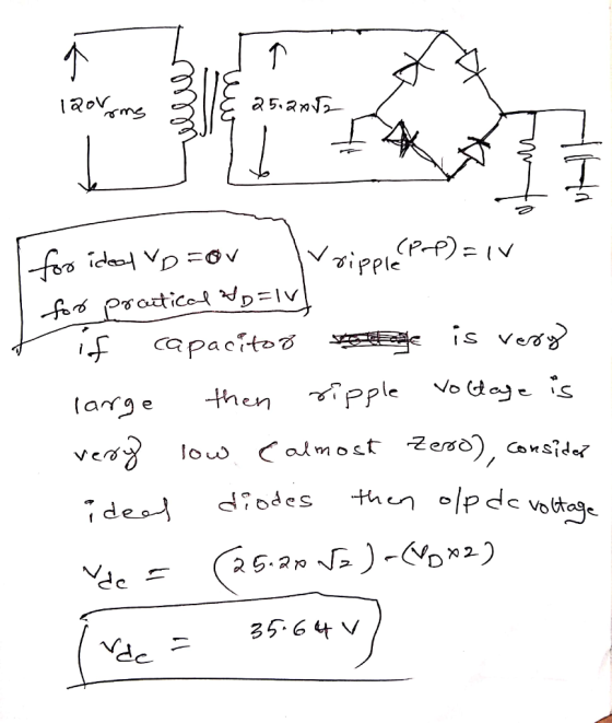
 two parts: need help understanding how to find ideal output DC
voltage given conditions, Than finding Capacitor that satisfies
conditions
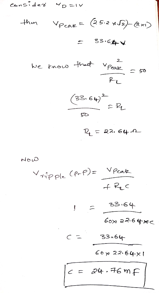
A classical rectifier uses a standard 120 V/25.2 V 60 Hz transformer. What ideal output DC voltage will result if a single-phase full-wave diode bridge is used with a large capacitor and the input is exactly 120 Vrms? Assume each diode's forward voltage drop is 1 V. Design a capacitor if the load is 50 W and the voltage ripple...
two parts: need help understanding how to find ideal output DC
voltage given conditions, Than finding Capacitor that satisfies
conditions
A classical rectifier uses a standard 120 V/25.2 V 60 Hz transformer. What ideal output DC voltage will result if a single-phase full-wave diode bridge is used with a large capacitor and the input is exactly 120 Vrms? Assume each diode's forward voltage drop is 1 V. Design a capacitor if the load is 50 W and the voltage ripple...
 Q5) Half-wave rectifier given below has an operating frequency of 120 Hz, while the transformer output voltage is 7.2 Vrms a) What is the rms value of the output voltage (V_OUT), if diode has an ON voltage of 1V? b) Minimum value of C to maintain the ripple voltage less than 0.35V, when R is 1 ohm? c) Draw thews and VOUT voltage waveform assuming vs_Ypsinωt D1 V S V OUT
Q5) Half-wave rectifier given below has an operating frequency...
Q5) Half-wave rectifier given below has an operating frequency of 120 Hz, while the transformer output voltage is 7.2 Vrms a) What is the rms value of the output voltage (V_OUT), if diode has an ON voltage of 1V? b) Minimum value of C to maintain the ripple voltage less than 0.35V, when R is 1 ohm? c) Draw thews and VOUT voltage waveform assuming vs_Ypsinωt D1 V S V OUT
Q5) Half-wave rectifier given below has an operating frequency...
 4.70 A full-wave bridge-rectifier circuit with a 500-22 load operates from a 120-V (rms) 60-Hz household supply through a 6-to-1 step-down transformer having a single Secondary winding. It uses four diodes, each of which can be modeled to have a 0.7-V drop for any current. What is the peak value of the rectified voltage across the load? For what fraction of a cycle does each diode conduct? What is the average voltage across the load? What is the average current...
 D *4.80 It is required to use a peak rectifier to design a de power supply that provides an average de output voltage of 12 V on which a maximum of ±1-V ripple is allowed. The rectifier feeds a load of 200 2. The rectifier is fed from the line voltage (120 V rms, 60 Hz) through a transformer. The diodes available have 0.7-V drop when conducting. If the designer opts for the half-wave circuit: (a) Specify the rms voltage...
 Design a FULL WAVE BRIDGE RECTIFIER circuit that will:
Take 120volts ac, 60 hz, sinusoidal waveform and convert
it to a “regulated “dc value
giving 12 volts +, - 1 volt across a 2000-ohm output
load resistor with no more than 2%
ripple voltage.
You may assume:
a. An ideal power transformer as discussed in class.
b. For hand computations, you must assume a diode given by
Figure 4.8 page 185.
c. A filter capacitor sized per the textbook equation...
Design a FULL WAVE BRIDGE RECTIFIER circuit that will:
Take 120volts ac, 60 hz, sinusoidal waveform and convert
it to a “regulated “dc value
giving 12 volts +, - 1 volt across a 2000-ohm output
load resistor with no more than 2%
ripple voltage.
You may assume:
a. An ideal power transformer as discussed in class.
b. For hand computations, you must assume a diode given by
Figure 4.8 page 185.
c. A filter capacitor sized per the textbook equation...
 Consider the single-phase full-wave rectifier circuit shown below with a sinusoidal input vs 120 Vrms at 60 Hz and a load R= 250 TiD DAZ 40 AD AD ww D (a) (b) Consider adding a filter capacitor to the full-wave rectifier in Problem 3 to reduce the output ripple (a) Calculate the minimum value of capacitance required to reduce the output voltage ripple to 1 % of the average value (b) Calculate the average output current (c) Calculate the average...
 part g
Q4. Most electronic systems need a dc voltage to work properly. The AC-to-DC power supply system is including a transformer, a rectifier and a capacitor input filter. The AC input voltage is 110 Vrms at 60 Hz. (a) Draw the full wave bridge rectifier circuit with transformer which steps down voltage to safer and lower levels that are more suitable for use with diodes (b) Show how the capacitor input filter connects to the rectifier output in the...
part g
Q4. Most electronic systems need a dc voltage to work properly. The AC-to-DC power supply system is including a transformer, a rectifier and a capacitor input filter. The AC input voltage is 110 Vrms at 60 Hz. (a) Draw the full wave bridge rectifier circuit with transformer which steps down voltage to safer and lower levels that are more suitable for use with diodes (b) Show how the capacitor input filter connects to the rectifier output in the...
 1. Power supply (ac to dc) design. [10 pts.] Design a full-wave bridge rectifier circuit to deliver 10 volts dc with less than 0.1 volt (peak to peak) ripple into a load drawing up to 10 mA. (a) Choose the appropriate ac input voltage from the transformer secondary assuming the usual voltage drops for silicon diodes. (b) Determine the correct capacitor value to ensure the specified ripple in your calculation (c) What fuse value should you select for the primary...
Most questions answered within 3 hours.
-
Which attribute allows you to specify a custom "thumbnail" for
multimedia elements?
asked 36 minutes ago -
How much 0.1200 M sodium hydroxide solution is need to titrate
14 mL of a 0.100...
asked 11 minutes ago -
An impulse is a change in momentum usually over
a short time. For which of the...
asked 15 minutes ago -
1a)When a 5000-kg roller coaster train full of riders approaches
the loading dock at a speed...
asked 36 minutes ago -
The Poseidon Swim Company produces swim trunks. The average
selling price for one of their swim...
asked 31 minutes ago -
If the elasticity of supply of a good is ∞, then its
A. supply curve is...
asked 17 minutes ago -
Write an application for the Shady Rest Hotel; the program
determines the price of a room....
asked 22 minutes ago -
USE THE FOLLOWING INFORMATION TO ANSWER THE NEXT (6)
QUESTIONS:
The following is a December 31,...
asked 38 minutes ago -
Suppose you plan to invest $5,000 each year (beginning at the
end of this year) into...
asked 28 minutes ago -
What is the cell potential of the following cell at 25
oC? Note Au is a...
asked 29 minutes ago -
DNA to Protein
Describe the mutation that created the HbS allele:
type of mutation, location of...
asked 35 minutes ago -
1. Why are the advantages and disadvantages of object-oriented
databases? 2. What are data marts? How...
asked 54 minutes ago