
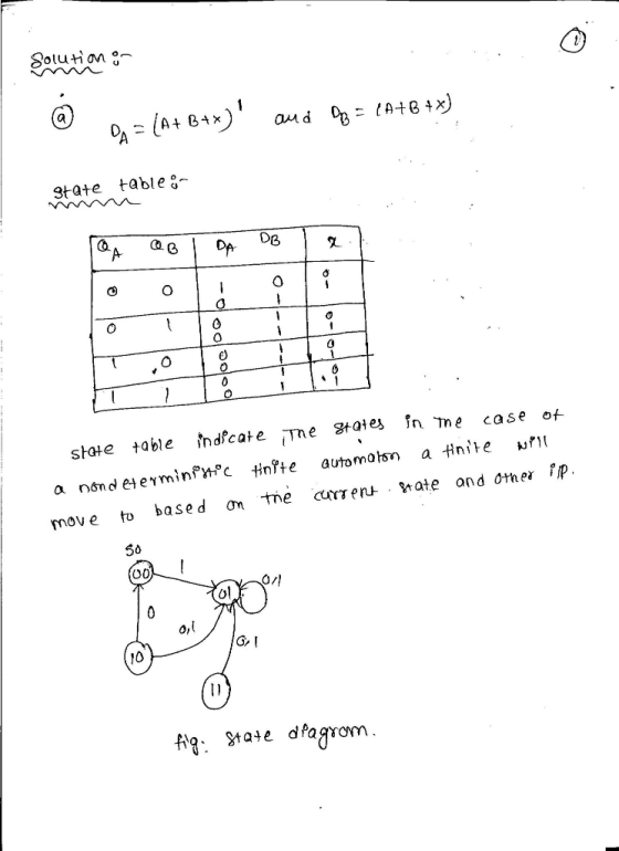
1. (a) Draw a state diagram and state table and show what if anything is wrong with the following synchronous state machine that has asynchronous input \(\mathrm{X}\) and state variables \(\mathrm{A} \& \mathrm{~B}\) ?
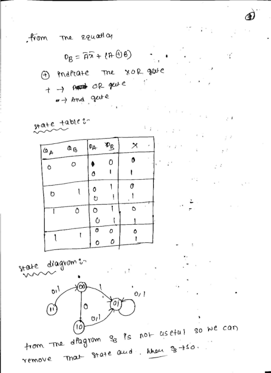
(b) If possible, draw a new circuit (without adding or removing any flip-flops) that has the same functionality but fixes any problem with the circuit. Also, show the new state diagram and state table.
Homework Answers

Add Answer to:
Draw a state diagram and state table and show what if anything is wrong with the following synchronous state machine
Draw a Moore-type state diagram and design a synchronous sequential circuit using D flip flops for...
Draw a Moore-type state diagram and design a synchronous sequential circuit using D flip flops for a 1-input/1-output "sequence detector" for the sequence 110 (be sure to recognize overlapping sequences). Draw the final circuit.
Draw a Moore-type state diagram and design a synchronous sequential circuit using D flip flops for...
Draw a Moore-type state diagram and design a synchronous sequential circuit using D flip flops for a 1-input/1-output "sequence detector" for the sequence 1001 (be sure to recognize overlapping sequences). Draw the final circuit.
HW#4-SYNCHRONOUS SEQUENTIAL CIRCUIT DESIGN Given the following state diagram, obtain the corresponding synchronous sequential circuit with...
 HW#4-SYNCHRONOUS SEQUENTIAL CIRCUIT DESIGN Given the following state diagram, obtain the corresponding synchronous sequential circuit with D flip-flops. Draw this circuit. (Use x as an input, and z as an output). 50 points] 1) 1/0 0/0 1/0
1. Given the state diagram shown below for a two-state synchronous sequential Mealy circuit with input....
 1. Given the state diagram shown below for a two-state synchronous sequential Mealy circuit with input. and output z, realize the circuit using D flip-flops. Your answer must include the state transition,excita- tion, and output tables, the excitation equation(s), and a labeled circuit diagram 1/0 2. Given the state diagram in Problem 1, realize the circuit using JK flip-flops. Your answer must include the state transition, excitation, and output tables, the excitation equation(s), and a labeled circuit diagram. 3. Given...
(25 pts) 5. The state diagram of a synchronous sequential circuit is shown below. X is...
 (25 pts) 5. The state diagram of a synchronous sequential circuit is shown below. X is an external input and Z is the output. (a) Design the circuit using D flip-flops. (b) Draw the logic diagram. A/0 B/0 Clas Сл D/0
1. FSM design. Design a clocked synchronous state machine with one input X, and an output...
 1. FSM design. Design a clocked synchronous state machine with one input X, and an output Z. Z is 1 if 010 sequence pattern has occurred in the input X Otherwise, the output should be 0 For solution: a) Draw the state diagram. b) Write the state/output table. xcitation eqations and output equatio You do not have to draw the circuit diagram. Hint: Three states are needed (two D flip-flops) A: initial state waiting for a 0' from X B:...
Problem 3:(10 pts) Design a synchronous machine (Transition Table, K-maps, Final Equations, Circu...
 Problem 3:(10 pts) Design a synchronous machine (Transition Table, K-maps, Final Equations, Circuit Diagram) that counts through the following sequence in the order shown below. Note, there are no inputs or output variables, so your Q values must reflect the Hex value listed B 742 D 9 3 0 and repeat a) using all D flip-flops and combinational logic (AND/OR/NOT gates only) b) using all T flip-flops and a multiplexer of size 8:1
Problem 3:(10 pts) Design a synchronous machine...
Problem 3:(10 pts) Design a synchronous machine (Transition Table, K-maps, Final Equations, Circuit Diagram) that counts through the following sequence in the order shown below. Note, there are no inputs or output variables, so your Q values must reflect the Hex value listed B 742 D 9 3 0 and repeat a) using all D flip-flops and combinational logic (AND/OR/NOT gates only) b) using all T flip-flops and a multiplexer of size 8:1
Problem 3:(10 pts) Design a synchronous machine...
Design a synchronous sequential counter circuit that has the state diagram shown in figure 1. Use...
 Design a synchronous sequential counter circuit that has the state diagram shown in figure 1. Use both D-type and T-type Flip Flops in your design. Show all your work in details. Extra credit will be given for implementation using other types of Flip Flops 3 4 Figure 1 Deliverables: 1. State Transition Table 2. K-Maps 3. Logical Expressions (Minimal Form) 4. Schematic Diagrams of the two designs 5. Verification steps for both designs.
Design a modulus-5 synchronous counter with D-type flip flops. Assume the next state for unused states are 000 rather than don't cares.
Design a modulus-5 synchronous counter with D-type flip flops. Assume the next state for unused states are 000 rather than don't cares. Set an output Z to high at the terminal count. (a) Determine state transition table. (b) Determine input equations for the flip flops and output equations. (c) Sketch the circuit diagram.
a 1 1 b с е f 1 1. Consider the following state table. Next State...
 a 1 1 b с е f 1 1. Consider the following state table. Next State Present State Output y = 0 x=1 r = 0 x=1 g b d a 0 0 0 d b g 0 0 0 b g 0 g d 0 (a) (4 points) Draw a state diagram based on the given state table. 1 e f a f 1 e 1 (b) (4 points) Obtain a reduced state table and draw the reduced state...
 HW#4-SYNCHRONOUS SEQUENTIAL CIRCUIT DESIGN Given the following state diagram, obtain the corresponding synchronous sequential circuit with D flip-flops. Draw this circuit. (Use x as an input, and z as an output). 50 points] 1) 1/0 0/0 1/0
 1. Given the state diagram shown below for a two-state synchronous sequential Mealy circuit with input. and output z, realize the circuit using D flip-flops. Your answer must include the state transition,excita- tion, and output tables, the excitation equation(s), and a labeled circuit diagram 1/0 2. Given the state diagram in Problem 1, realize the circuit using JK flip-flops. Your answer must include the state transition, excitation, and output tables, the excitation equation(s), and a labeled circuit diagram. 3. Given...
 (25 pts) 5. The state diagram of a synchronous sequential circuit is shown below. X is an external input and Z is the output. (a) Design the circuit using D flip-flops. (b) Draw the logic diagram. A/0 B/0 Clas Сл D/0
 1. FSM design. Design a clocked synchronous state machine with one input X, and an output Z. Z is 1 if 010 sequence pattern has occurred in the input X Otherwise, the output should be 0 For solution: a) Draw the state diagram. b) Write the state/output table. xcitation eqations and output equatio You do not have to draw the circuit diagram. Hint: Three states are needed (two D flip-flops) A: initial state waiting for a 0' from X B:...
 Problem 3:(10 pts) Design a synchronous machine (Transition Table, K-maps, Final Equations, Circuit Diagram) that counts through the following sequence in the order shown below. Note, there are no inputs or output variables, so your Q values must reflect the Hex value listed B 742 D 9 3 0 and repeat a) using all D flip-flops and combinational logic (AND/OR/NOT gates only) b) using all T flip-flops and a multiplexer of size 8:1
Problem 3:(10 pts) Design a synchronous machine...
Problem 3:(10 pts) Design a synchronous machine (Transition Table, K-maps, Final Equations, Circuit Diagram) that counts through the following sequence in the order shown below. Note, there are no inputs or output variables, so your Q values must reflect the Hex value listed B 742 D 9 3 0 and repeat a) using all D flip-flops and combinational logic (AND/OR/NOT gates only) b) using all T flip-flops and a multiplexer of size 8:1
Problem 3:(10 pts) Design a synchronous machine...
 Design a synchronous sequential counter circuit that has the state diagram shown in figure 1. Use both D-type and T-type Flip Flops in your design. Show all your work in details. Extra credit will be given for implementation using other types of Flip Flops 3 4 Figure 1 Deliverables: 1. State Transition Table 2. K-Maps 3. Logical Expressions (Minimal Form) 4. Schematic Diagrams of the two designs 5. Verification steps for both designs.
 a 1 1 b с е f 1 1. Consider the following state table. Next State Present State Output y = 0 x=1 r = 0 x=1 g b d a 0 0 0 d b g 0 0 0 b g 0 g d 0 (a) (4 points) Draw a state diagram based on the given state table. 1 e f a f 1 e 1 (b) (4 points) Obtain a reduced state table and draw the reduced state...
Most questions answered within 3 hours.
-
Write the ionic equations for the first stage of salts
hydrolysis.
Anion, Cation?
Na2S
NiSO4
K2SO4...
asked 1 hour ago -
suppose there is a normally distributed population with a mean of
250 and a standard deviation...
asked 1 hour ago -
Question Three
Suppose you as project manager are using the Waterfall
development methodology on a large...
asked 2 hours ago -
Which statement is not true about welfare in Canada?
A.Benefits typically vary based on one's ability...
asked 3 hours ago -
Please help me with FLOWCHART and UML diagram for class,
thank you!
#include <iostream>
#include <fstream>...
asked 4 hours ago -
3. Describe the “logic circuit” of the Lac operon. Which
proteins are bound or not to...
asked 4 hours ago -
Ayesha’s adjusted gross income is $60,000 in 2019. She donated a
piece of artwork with a...
asked 4 hours ago -
For Dijkstra’s shortest path algorithm:
a. Give the Big-O time for Dijkstra’s shortest path algorithm
and...
asked 4 hours ago -
Phosphorus violates the 'octet rule' in biological molecules,
forming more covalent bonds than expected based on...
asked 4 hours ago -
A 1.3 eV electron has a 10-4 probability of tunneling
through a 2.4 eV potential barrier....
asked 4 hours ago -
What is the one ingredient that is common to being successful
with all stakeholders?
profit
trust...
asked 4 hours ago -
Write an assembly language 32 bit program that reads in lines of
text by a .txt...
asked 4 hours ago