
Homework Answers

Add Answer to:
(25 pts) 5. The state diagram of a synchronous sequential circuit is shown below. X is...
HW#4-SYNCHRONOUS SEQUENTIAL CIRCUIT DESIGN Given the following state diagram, obtain the corresponding synchronous sequential circuit with...
 HW#4-SYNCHRONOUS SEQUENTIAL CIRCUIT DESIGN Given the following state diagram, obtain the corresponding synchronous sequential circuit with D flip-flops. Draw this circuit. (Use x as an input, and z as an output). 50 points] 1) 1/0 0/0 1/0
1. Given the state diagram shown below for a two-state synchronous sequential Mealy circuit with input....
 1. Given the state diagram shown below for a two-state synchronous sequential Mealy circuit with input. and output z, realize the circuit using D flip-flops. Your answer must include the state transition,excita- tion, and output tables, the excitation equation(s), and a labeled circuit diagram 1/0 2. Given the state diagram in Problem 1, realize the circuit using JK flip-flops. Your answer must include the state transition, excitation, and output tables, the excitation equation(s), and a labeled circuit diagram. 3. Given...
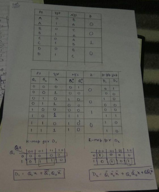
5) A single-input (x) single-output(z) synchronous sequential circuit is required to operate as follows: i) The...
 5) A single-input (x) single-output(z) synchronous sequential circuit is required to operate as follows: i) The circuit is put to a specific initial state (call this state A) ii) Starting from state A, the circuit will give a 1 output when the input sequence up to and including the present time contains an odd number of 0's and an odd number of l's: the circuit will give a 0 output at all other times An example input and corresponding output...
Draw a Moore-type state diagram and design a synchronous sequential circuit using D flip flops for...
Draw a Moore-type state diagram and design a synchronous sequential circuit using D flip flops for a 1-input/1-output "sequence detector" for the sequence 110 (be sure to recognize overlapping sequences). Draw the final circuit.
Draw a Moore-type state diagram and design a synchronous sequential circuit using D flip flops for...
Draw a Moore-type state diagram and design a synchronous sequential circuit using D flip flops for a 1-input/1-output "sequence detector" for the sequence 1001 (be sure to recognize overlapping sequences). Draw the final circuit.
Thc state transition table bclow is for a sequential circuit with onc input X and onc output Y. The circuit has two state variables A and B, and synchronous input Reset that resets the circuit to sta...
 Thc state transition table bclow is for a sequential circuit with onc input X and onc output Y. The circuit has two state variables A and B, and synchronous input Reset that resets the circuit to state AB-01 when Reset 1: Present State Next State Output X-0 A B A B 0 Reset State 0 0 (9 points) Implement the sequential circuit using minimum number of logic gates and rising- edge triggered D-FFs and draw the logic diagram of the...
Design a synchronous sequential counter circuit that has the state diagram shown in figure 1. Use...
 Design a synchronous sequential counter circuit that has the state diagram shown in figure 1. Use both D-type and T-type Flip Flops in your design. Show all your work in details. Extra credit will be given for implementation using other types of Flip Flops 3 4 Figure 1 Deliverables: 1. State Transition Table 2. K-Maps 3. Logical Expressions (Minimal Form) 4. Schematic Diagrams of the two designs 5. Verification steps for both designs.
The sequential circuit shown below has two flip-flops A and B and one input x. It...
 The sequential circuit shown below has two flip-flops A and B and one input x. It consists of a combinatorial logic connected to the flip-flops, as shown in the Figure 1. Below. Analyze the sequential circuit below: A J A' K Q lo B 2-to-1 MUX Y J Q 11 S B K CLK Figure 1a. Sequential Circuit a) Derive the next state equations for the sequential circuit above: find expressions for JA and KA and Jb and KB as...
A sequential circuit with two flip flops, A and B; one input, x; and one output...
A sequential circuit with two flip flops, A and B; one input, x; and one output y, is specified by the following next-state and output equations. B(t+1)=Ax A(t+1)=A'B+Bx'+AB'x a) List the circuit state table and draw the corresponding state diagram. b) Draw the logic diagram of the circuit using only, one D-type and one T-type flip flops, one 2X4 decoder and one 2-input OR gate. The complement of the input variable, x is not available.
03: 6 marks) Sequential circuit that has two flip-flops A and B and one input x...
 03: 6 marks) Sequential circuit that has two flip-flops A and B and one input x and a constant 'l'. It consists of a combinatorial logic connected to the JK flip-flops, as shown in Figure below. a. (2 marks) Derive the next state and output equations. b. (2 marks) Derive the state table of the sequential circuit. c. (2 marks) Draw the corresponding state diagram. K ā
 HW#4-SYNCHRONOUS SEQUENTIAL CIRCUIT DESIGN Given the following state diagram, obtain the corresponding synchronous sequential circuit with D flip-flops. Draw this circuit. (Use x as an input, and z as an output). 50 points] 1) 1/0 0/0 1/0
 1. Given the state diagram shown below for a two-state synchronous sequential Mealy circuit with input. and output z, realize the circuit using D flip-flops. Your answer must include the state transition,excita- tion, and output tables, the excitation equation(s), and a labeled circuit diagram 1/0 2. Given the state diagram in Problem 1, realize the circuit using JK flip-flops. Your answer must include the state transition, excitation, and output tables, the excitation equation(s), and a labeled circuit diagram. 3. Given...
 5) A single-input (x) single-output(z) synchronous sequential circuit is required to operate as follows: i) The circuit is put to a specific initial state (call this state A) ii) Starting from state A, the circuit will give a 1 output when the input sequence up to and including the present time contains an odd number of 0's and an odd number of l's: the circuit will give a 0 output at all other times An example input and corresponding output...
 Thc state transition table bclow is for a sequential circuit with onc input X and onc output Y. The circuit has two state variables A and B, and synchronous input Reset that resets the circuit to state AB-01 when Reset 1: Present State Next State Output X-0 A B A B 0 Reset State 0 0 (9 points) Implement the sequential circuit using minimum number of logic gates and rising- edge triggered D-FFs and draw the logic diagram of the...
 Design a synchronous sequential counter circuit that has the state diagram shown in figure 1. Use both D-type and T-type Flip Flops in your design. Show all your work in details. Extra credit will be given for implementation using other types of Flip Flops 3 4 Figure 1 Deliverables: 1. State Transition Table 2. K-Maps 3. Logical Expressions (Minimal Form) 4. Schematic Diagrams of the two designs 5. Verification steps for both designs.
 The sequential circuit shown below has two flip-flops A and B and one input x. It consists of a combinatorial logic connected to the flip-flops, as shown in the Figure 1. Below. Analyze the sequential circuit below: A J A' K Q lo B 2-to-1 MUX Y J Q 11 S B K CLK Figure 1a. Sequential Circuit a) Derive the next state equations for the sequential circuit above: find expressions for JA and KA and Jb and KB as...
 03: 6 marks) Sequential circuit that has two flip-flops A and B and one input x and a constant 'l'. It consists of a combinatorial logic connected to the JK flip-flops, as shown in Figure below. a. (2 marks) Derive the next state and output equations. b. (2 marks) Derive the state table of the sequential circuit. c. (2 marks) Draw the corresponding state diagram. K ā
Most questions answered within 3 hours.
-
Write a program to solve the Josephus problem, with the following
modification:
Sample Input:
./a.out n...
asked 5 minutes ago -
At the start of a CD it is spinning at a rate of 525 rpm
(revolutions...
asked 41 minutes ago -
4. Without doing any calculations, predict whether the observed
∆T would increase, decrease or remain the...
asked 1 hour ago -
Based on the range, which of the following sets of scores has
the greatest variability? 3,...
asked 3 hours ago -
Ripples in a pond travel at a velocity of 3 m/s with one peak
passing a...
asked 2 hours ago -
A man stands on the roof of a building of height 13.0 mm and
throws a...
asked 3 hours ago -
The extent to which assets are financed by borrowed funds and
other liabilities is indicated by:...
asked 4 hours ago -
Explain in detail
Germany is the fifth largest economy
explain what goods and services Germany specializes...
asked 4 hours ago -
The density of platinum is 21.45 g/mL. If a cube of platinum
with a mass of...
asked 4 hours ago -
Accounts Receivable
Sales
A/R Posting
Extended Sales Invoice
Packing Slip
Compare invoice to packing slip 2...
asked 4 hours ago -
Michaella, age 23, is a full-time law student and is claimed by
her parents as a...
asked 4 hours ago -
Why are polymers not typically casted into products?
asked 4 hours ago