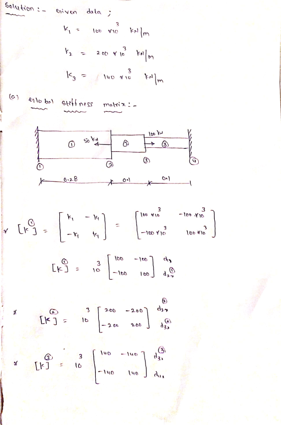
For the system shown below, (a) the global stiffness matrix (b)displacements of nodes 2 and 3 (c)the reaction forces at nodes 1 and 4 (d)the force in the members


Homework Answers
The solution of the given problem is given below
![enlobal stiffness matria [k] = [k + [ k) [k] + [k] du 4. น dza dur loc -100 0 3 - 100 300 -200 [K] 10 O -200 340 -luo -luo lu](http://img.homeworklib.com/questions/ea0700c0-90d0-11eb-805c-ff3f3275fb64.png?x-oss-process=image/resize,w_560)
![The al Peaction torce nodes and From global 3 Fi lo v { lot or 4.838 xios] R 4,838 ka Ru -4 to} i do to 140 3.22 58 y 10 -US.](http://img.homeworklib.com/questions/eb6df780-90d0-11eb-a3b2-657665451bdb.png?x-oss-process=image/resize,w_560)

Add Answer to:
For the system shown below, (a) the global stiffness
matrix (b)displacements of nodes 2 and 3...
For the spring assemblage shown in Figure 2-13, obtain (a) the global stiffness matrix, (b) the displacements of nodes 2-4, (c) the global nodal forces, and (d) the local element forces.
For the spring assemblage shown in Figure 2-13, obtain (a) the global stiffness matrix, (b) the displacements of nodes 2-4, (c) the global nodal forces, and (d) the local element forces. Node l is fixed while node 5 is given a fixed, known displacement δ= 20.0 mm. The spring constants are all equal to k = 200 kN/m.
2 k3 2 3 4 a. (10 points) Obtain the global stiffness matrix K using direct...
 2 k3 2 3 4 a. (10 points) Obtain the global stiffness matrix K using direct stiffness method (k1- 100 1b/in, k2 200 lb/in, k3 3001b/in, P-500 Ib). (10 points) If nodes 1 and 4 are fixed and a force P acts on node 2 in the positive x direction, fin the values for the displacements of nodes 2 and 3. b. c. (10 points) Deter odes 1 and 4
Problem 4, (20%) For the case shown determine the displacements and the slopes at the nodes,...
 Problem 4, (20%) For the case shown determine the displacements and the slopes at the nodes, the forces in each element, and the reactions. Also, draw the shear force and bending moment diagrams. 24 KN 4 m 4 m E = 70 GPa 1 = 2 x 10⁻⁴ m > k = 200 kN/m
Using the stiffness method, determine the axial forces within members and the displacements of jo...
 Using the stiffness method, determine the axial forces within
members and the displacements of joints of the truss shown in the
Figure 1. The truss was built using 50 mm x 50 mm x 3 mm SHS with
E= 200 GPa (approx). (Cross members BD and CE are not connected at
the middle)
(a) Show local stiffness matrices for each member and the
assembled global stiffness matrix. Show your step by step solution.
(30 Marks)
(b) Use an appropriate method...
Using the stiffness method, determine the axial forces within
members and the displacements of joints of the truss shown in the
Figure 1. The truss was built using 50 mm x 50 mm x 3 mm SHS with
E= 200 GPa (approx). (Cross members BD and CE are not connected at
the middle)
(a) Show local stiffness matrices for each member and the
assembled global stiffness matrix. Show your step by step solution.
(30 Marks)
(b) Use an appropriate method...
Q2b Using the direct stiffness method, determine for the beam shown: a) the displacements and rotations...
 Q2b Using the direct stiffness method, determine for the beam shown: a) the displacements and rotations of the nodes, the shear forces and moments at the nodes b) Subsequently, draw the deflected shape, shear force and bending moment diagrams. 4m rM Take: El 5 X 10⁶ Nm2, F 10 kN and w 4 kN/m.
Using the Stiffness Method procedure identify nodes, elements and degrees of freedom (neglect axial stiffness) for the beam shown below. Form member and structure stiffness matrices and compute displ...
 Using the Stiffness Method procedure identify nodes, elements and degrees of freedom (neglect axial stiffness) for the beam shown below. Form member and structure stiffness matrices and compute displacements, reactions and internal forces developed in the beam Note that there is a hinge at B. Take E = 250 GPa, 1-2000 cm 10 kN 2 kN/m 5 kN-m 10 m
Using the Stiffness Method procedure identify nodes, elements and degrees of freedom (neglect axial stiffness) for the beam shown below....
Using the Stiffness Method procedure identify nodes, elements and degrees of freedom (neglect axial stiffness) for the beam shown below. Form member and structure stiffness matrices and compute displacements, reactions and internal forces developed in the beam Note that there is a hinge at B. Take E = 250 GPa, 1-2000 cm 10 kN 2 kN/m 5 kN-m 10 m
Using the Stiffness Method procedure identify nodes, elements and degrees of freedom (neglect axial stiffness) for the beam shown below....
Problem 2 [Required]: For the truss below (and using the Stiffness Method): (a) Determine the global...
 Problem 2 [Required]: For the truss below (and using the Stiffness Method): (a) Determine the global stiffness matrix; (b) Calculate the vertical and horizontal displacement at joint B; (c) Calculate the force in members 1 and 5; (d) Calculate the reaction forces. NOTE: Joint A is pinned and Joint D is a roller. AE is constant. Use the chart below for selecting near and far nodes and use the provided coordination numbers. u2 2m 5 2 kN 3 Element 2...
Week 7. Question 1: Use the stiffness method to determine the horizontal and vertical displacements at...
 Week 7. Question 1: Use the stiffness method to determine the horizontal and vertical displacements at joint A. For all members, E-206.8 GPa and A - 1290 mm? Take a - 8 mandb-6.1 m B 2 انها 160 kN Solve the problem by following these steps Part 1) Calculate the stiffness matrix of each member in the global coordinate system. Check kna (the value at the second column and second row) in each member stiffness matrix a) Member 1: ky...
Using the Stiffness Method procedure identify nodes, elements and degrees of freedom (neglect axial stiffness) for the beam shown below. Form member and structure stiffness matrices and compute di...
 Using the Stiffness Method procedure identify nodes, elements and degrees of freedom (neglect axial stiffness) for the beam shown below. Form member and structure stiffness matrices and compute displacements, reactions and internal forces developed in the beam. Note that there is a hinge at B. Take E= 250 G Pa, 1 = 2000 cm- 10 kN 5 kN-m 2 kN/m 10 m
Using the Stiffness Method procedure identify nodes, elements and degrees of freedom (neglect axial stiffness) for the beam...
Using the Stiffness Method procedure identify nodes, elements and degrees of freedom (neglect axial stiffness) for the beam shown below. Form member and structure stiffness matrices and compute displacements, reactions and internal forces developed in the beam. Note that there is a hinge at B. Take E= 250 G Pa, 1 = 2000 cm- 10 kN 5 kN-m 2 kN/m 10 m
Using the Stiffness Method procedure identify nodes, elements and degrees of freedom (neglect axial stiffness) for the beam...
a. Compute the total stiffness matrix [K] of the assemblage shown in Figure 3-1 by superimposing...
 a. Compute the total stiffness matrix [K] of the assemblage shown in Figure 3-1 by superimposing the stiffness matrices of the individual bars. Note that should be in terms of A. As, A, E, E E, L. and L. Here A, E, and are generic symbols used for cross-sectional area modulus of elasticity, and length, respectively Figure P3-1 Now let As - Ag-A-A.E E, E E and L-L L -L nodes 1 and 4 are fixed and a force Pacts...
 2 k3 2 3 4 a. (10 points) Obtain the global stiffness matrix K using direct stiffness method (k1- 100 1b/in, k2 200 lb/in, k3 3001b/in, P-500 Ib). (10 points) If nodes 1 and 4 are fixed and a force P acts on node 2 in the positive x direction, fin the values for the displacements of nodes 2 and 3. b. c. (10 points) Deter odes 1 and 4
 Problem 4, (20%) For the case shown determine the displacements and the slopes at the nodes, the forces in each element, and the reactions. Also, draw the shear force and bending moment diagrams. 24 KN 4 m 4 m E = 70 GPa 1 = 2 x 10⁻⁴ m > k = 200 kN/m
 Using the stiffness method, determine the axial forces within
members and the displacements of joints of the truss shown in the
Figure 1. The truss was built using 50 mm x 50 mm x 3 mm SHS with
E= 200 GPa (approx). (Cross members BD and CE are not connected at
the middle)
(a) Show local stiffness matrices for each member and the
assembled global stiffness matrix. Show your step by step solution.
(30 Marks)
(b) Use an appropriate method...
Using the stiffness method, determine the axial forces within
members and the displacements of joints of the truss shown in the
Figure 1. The truss was built using 50 mm x 50 mm x 3 mm SHS with
E= 200 GPa (approx). (Cross members BD and CE are not connected at
the middle)
(a) Show local stiffness matrices for each member and the
assembled global stiffness matrix. Show your step by step solution.
(30 Marks)
(b) Use an appropriate method...
 Q2b Using the direct stiffness method, determine for the beam shown: a) the displacements and rotations of the nodes, the shear forces and moments at the nodes b) Subsequently, draw the deflected shape, shear force and bending moment diagrams. 4m rM Take: El 5 X 10⁶ Nm2, F 10 kN and w 4 kN/m.
 Using the Stiffness Method procedure identify nodes, elements and degrees of freedom (neglect axial stiffness) for the beam shown below. Form member and structure stiffness matrices and compute displacements, reactions and internal forces developed in the beam Note that there is a hinge at B. Take E = 250 GPa, 1-2000 cm 10 kN 2 kN/m 5 kN-m 10 m
Using the Stiffness Method procedure identify nodes, elements and degrees of freedom (neglect axial stiffness) for the beam shown below....
Using the Stiffness Method procedure identify nodes, elements and degrees of freedom (neglect axial stiffness) for the beam shown below. Form member and structure stiffness matrices and compute displacements, reactions and internal forces developed in the beam Note that there is a hinge at B. Take E = 250 GPa, 1-2000 cm 10 kN 2 kN/m 5 kN-m 10 m
Using the Stiffness Method procedure identify nodes, elements and degrees of freedom (neglect axial stiffness) for the beam shown below....
 Problem 2 [Required]: For the truss below (and using the Stiffness Method): (a) Determine the global stiffness matrix; (b) Calculate the vertical and horizontal displacement at joint B; (c) Calculate the force in members 1 and 5; (d) Calculate the reaction forces. NOTE: Joint A is pinned and Joint D is a roller. AE is constant. Use the chart below for selecting near and far nodes and use the provided coordination numbers. u2 2m 5 2 kN 3 Element 2...
 Week 7. Question 1: Use the stiffness method to determine the horizontal and vertical displacements at joint A. For all members, E-206.8 GPa and A - 1290 mm? Take a - 8 mandb-6.1 m B 2 انها 160 kN Solve the problem by following these steps Part 1) Calculate the stiffness matrix of each member in the global coordinate system. Check kna (the value at the second column and second row) in each member stiffness matrix a) Member 1: ky...
 Using the Stiffness Method procedure identify nodes, elements and degrees of freedom (neglect axial stiffness) for the beam shown below. Form member and structure stiffness matrices and compute displacements, reactions and internal forces developed in the beam. Note that there is a hinge at B. Take E= 250 G Pa, 1 = 2000 cm- 10 kN 5 kN-m 2 kN/m 10 m
Using the Stiffness Method procedure identify nodes, elements and degrees of freedom (neglect axial stiffness) for the beam...
Using the Stiffness Method procedure identify nodes, elements and degrees of freedom (neglect axial stiffness) for the beam shown below. Form member and structure stiffness matrices and compute displacements, reactions and internal forces developed in the beam. Note that there is a hinge at B. Take E= 250 G Pa, 1 = 2000 cm- 10 kN 5 kN-m 2 kN/m 10 m
Using the Stiffness Method procedure identify nodes, elements and degrees of freedom (neglect axial stiffness) for the beam...
 a. Compute the total stiffness matrix [K] of the assemblage shown in Figure 3-1 by superimposing the stiffness matrices of the individual bars. Note that should be in terms of A. As, A, E, E E, L. and L. Here A, E, and are generic symbols used for cross-sectional area modulus of elasticity, and length, respectively Figure P3-1 Now let As - Ag-A-A.E E, E E and L-L L -L nodes 1 and 4 are fixed and a force Pacts...
Most questions answered within 3 hours.
-
. For this set of questions, determine what
proportion of a normal distribution is located betweeneach...
asked 8 minutes ago -
A college student is employed as a door-to-door newspaper
salesman. Historical data suggests that the student...
asked 1 hour ago -
MATLAB HW 11 problem using Switch Case and Input commands
Write a script file that calculates...
asked 47 minutes ago -
Considering gravitational time dilation, calculate the time that
passes in Earth’s surface while 1 hour passes...
asked 1 hour ago -
Minitab Problem: Take the Lake Hume June rainfall data and find
use the processes outlined in...
asked 2 hours ago -
X Company is trying to decide whether to continue using old
equipment to make Product A...
asked 2 hours ago -
IN PYTHON ONLY !! Program 2: Re-work
program #5 (WeeklyHours) from the previous assignment such that...
asked 2 hours ago -
The average length of time between arrivals at a turnpike
toll-booth is 26 seconds. What is...
asked 4 hours ago -
(a) A piston at 6.1 atm contains a gas that occupies a volume of
3.5 L....
asked 5 hours ago -
Please answer true or false. Words
cannot be changed or added in to make it true...
asked 5 hours ago -
An empty test tube weighs 15.923 grams. Then,
MgCl2•6H2O is added into the test tube. After...
asked 5 hours ago -
Assume memory access is 10 units of time and disk access is
10000 units of time....
asked 6 hours ago