
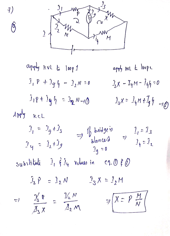
7.- The Wheatstone Bridge. The circuit shown in the figure, called a Wheatstone bridge, is used to determine the value of an unknown resistor \(X\) by comparison with three resistors \(M, N\), and \(P\) whose resistances can be varied. For each setting, the resistance of each resistor is precisely known. With switches \(K_{1}\) and \(K_{2}\) closed, these resistors are varied until the current in the galvanometer \(G\) is zero; the bridge is then said to be balanced. (a) Show that under this condition the unknown resistance is given by \(X=M P / N\). (This method permits very high precision in comparing resistors.) (b) If the galvanometer \(G\)
shows zero deflection when \(N=1850.0 \Omega, M=150.00 \Omega\) and \(P=133.48 \Omega\) what is the unknown resistance \(X\) if \(E=120\) V?
Homework Answers

Add Answer to:
7.- The Wheatstone Bridge. The circuit shown in the figure, called a Wheatstone bridge, is used...
Consider the circuit shown below which is used to monitor the io...
 Consider the circuit shown below which is used to monitor the force applied to a strain gauge. The circuit is called a "Wheatstone Bridge". The current-measuring device is called a "Galvanometer", and it has an internal resistance of \(50 \Omega\). Resistor \(R_{3}\) represents a force-sensitive resistor (strain gauge) whose resistance increases with bending moment.For the resistor values shown, the circuit is balanced and no current will flow through the Galvanometer. What will be the magnitude and direction of the current...
To what value must R3 be adjusted to balance a Wheatstone bridge it the unknown resistance...
 To what value must R3 be adjusted to balance a Wheatstone bridge it the unknown resistance Rx is 155 Ohm. R1 is 46.5 Ohm, and R2 is 185 Ohm? The bridge is said to be balanced when the current through the galvanometer (G) is zero. Number ________ Ohm
fast please 2. In the shown Wheatstone bridge circuit, R., and R, are the two portions...
 fast please
2. In the shown Wheatstone bridge circuit, R., and R, are the two portions of a I m single wire with a sliding contact. If the bridge is balanced when L - 46 cm and R, -100 2. What is the value of the unknown resistor R.
fast please
2. In the shown Wheatstone bridge circuit, R., and R, are the two portions of a I m single wire with a sliding contact. If the bridge is balanced when L - 46 cm and R, -100 2. What is the value of the unknown resistor R.
Q.2. (a) From the data given below, the fastest and the slowest photoconductive cells are used in a Wheatstone bridge as shown in the adjoining figure. What will be the output voltage of the circuit...
 Q.2. (a) From the data given below, the fastest and the slowest photoconductive cells are used in a Wheatstone bridge as shown in the adjoining figure. What will be the output voltage of the circuit 10"sec after the same amount of light falls on both the photoconductors? Nar Photo- Time conductor Constant Resistance light CdS CdSe PbS PbSe Dark Resistance in | 30 kΩ | 30 kΩ po쓰 100ms | 100 kΩ 10ms 400us 100 k(2 | 200 kΩ |...
As shown in the figure, a charge +2e is at the origin and an unknown charge...
 As shown in the figure, a charge +2e is at the origin and an unknown charge Q is at x = +4.0 nm. If the net electric force on a small positive test charge is zero atx =-1 nm, what is the magnitude and sign of the unknown charge? test charge charge q +2e unknown charge Q X=-1 nm x=0 x=+4 nm 0-50e +50e 0 -0.02 +0.02e 0-25e The figure below shows a proton and an electron separated by a...
1 A repelling force must occur between two charged objects under which conditions?
 1 A repelling force must occur between two charged objects under which conditions? a. charges are of unlike signs b. charges are of like signs c. charges are of equal magnitude d.charges are of unequal magnitude 2 Two point charges are 4 cm apart. They are moved to a new separation of 2 cm. By what factor does the electric force between them change? a.2 b. 1/2 c.4 d. 1/4 3. By mapping the equipotential lines, you can draw a. the charge b. the electric field...
5. Material with uniform resistivity is formed into a wedge as shown in Figure 27.19. Show...
 5. Material with uniform resistivity is formed into a wedge as shown in Figure 27.19. Show that there sistance between face A and face of this wedges given by 6. In the circuit of Fig. 32-30, 1200 V, C-6,50 F, R.-R.-R.-7.30 x 10" n. With C completely unchanged the switch is suddenly closed t o la Determine the currents through each resistor for t=0 and 1 Draw qualitatively a graph of the potential drop V, across R. from O to...
1. Consider the circuit shown below which shows a battery connected to some resistors battery is...
 1. Consider the circuit shown below which shows a battery connected to some resistors battery is along with some switches which will be toggled opened or closed at different times. The a15V battery. Resistor R1 is 100?, R2 is 200?, and Cl is 110 ?F, C2 is 80 ?F, and C3 is A stopwatch is started at time t1-0 ms. At that time, switch S1 is closed and all other switches are open and the capacitor is allowed to charge...
Determine the voltage across resistor R2=40ΩR2=40Ω in the circuit shown in (Figure 1), where vs=60Vvs=60V, R1=20ΩR1=20Ω,...
 Determine the voltage across resistor R2=40ΩR2=40Ω in the
circuit shown in (Figure 1), where vs=60Vvs=60V, R1=20ΩR1=20Ω,
R3=30ΩR3=30Ω, and R4=40Ω
Question 6 Part A Determine the voltage across resistor R2 = 40 2 in the circuit shown in (Figure 1), where us = 60 V, R1 = 20 12 R3 = 30 12, and R4 = 40 12 Express your answer in volts to three significant figures. View Available Hint(s) Learning Goal: To determine the voltage, current, and power of circuit...
Determine the voltage across resistor R2=40ΩR2=40Ω in the
circuit shown in (Figure 1), where vs=60Vvs=60V, R1=20ΩR1=20Ω,
R3=30ΩR3=30Ω, and R4=40Ω
Question 6 Part A Determine the voltage across resistor R2 = 40 2 in the circuit shown in (Figure 1), where us = 60 V, R1 = 20 12 R3 = 30 12, and R4 = 40 12 Express your answer in volts to three significant figures. View Available Hint(s) Learning Goal: To determine the voltage, current, and power of circuit...
Vss (b) Find ( Drav amp the variation of D 7.103 Figure P7.103 feedback-bias circuit of...
 Vss (b) Find ( Drav amp the variation of D 7.103 Figure P7.103 feedback-bias circuit of Fig. 7.50. Using a 5-V supply with an NMOS transistor for which V, =0.8 V, k. = 8 mA/V =0, provide a design that biases the transistor at I = 1 nA, with Vps large enough to allow saturation operation for a 2-V negative signal swing at the drain. Use 22 MS2 as the largest resistor in the feedback-bias network. What values of R...
 Consider the circuit shown below which is used to monitor the force applied to a strain gauge. The circuit is called a "Wheatstone Bridge". The current-measuring device is called a "Galvanometer", and it has an internal resistance of \(50 \Omega\). Resistor \(R_{3}\) represents a force-sensitive resistor (strain gauge) whose resistance increases with bending moment.For the resistor values shown, the circuit is balanced and no current will flow through the Galvanometer. What will be the magnitude and direction of the current...
 To what value must R3 be adjusted to balance a Wheatstone bridge it the unknown resistance Rx is 155 Ohm. R1 is 46.5 Ohm, and R2 is 185 Ohm? The bridge is said to be balanced when the current through the galvanometer (G) is zero. Number ________ Ohm
 fast please
2. In the shown Wheatstone bridge circuit, R., and R, are the two portions of a I m single wire with a sliding contact. If the bridge is balanced when L - 46 cm and R, -100 2. What is the value of the unknown resistor R.
fast please
2. In the shown Wheatstone bridge circuit, R., and R, are the two portions of a I m single wire with a sliding contact. If the bridge is balanced when L - 46 cm and R, -100 2. What is the value of the unknown resistor R.
 Q.2. (a) From the data given below, the fastest and the slowest photoconductive cells are used in a Wheatstone bridge as shown in the adjoining figure. What will be the output voltage of the circuit 10"sec after the same amount of light falls on both the photoconductors? Nar Photo- Time conductor Constant Resistance light CdS CdSe PbS PbSe Dark Resistance in | 30 kΩ | 30 kΩ po쓰 100ms | 100 kΩ 10ms 400us 100 k(2 | 200 kΩ |...
 As shown in the figure, a charge +2e is at the origin and an unknown charge Q is at x = +4.0 nm. If the net electric force on a small positive test charge is zero atx =-1 nm, what is the magnitude and sign of the unknown charge? test charge charge q +2e unknown charge Q X=-1 nm x=0 x=+4 nm 0-50e +50e 0 -0.02 +0.02e 0-25e The figure below shows a proton and an electron separated by a...
 5. Material with uniform resistivity is formed into a wedge as shown in Figure 27.19. Show that there sistance between face A and face of this wedges given by 6. In the circuit of Fig. 32-30, 1200 V, C-6,50 F, R.-R.-R.-7.30 x 10" n. With C completely unchanged the switch is suddenly closed t o la Determine the currents through each resistor for t=0 and 1 Draw qualitatively a graph of the potential drop V, across R. from O to...
 1. Consider the circuit shown below which shows a battery connected to some resistors battery is along with some switches which will be toggled opened or closed at different times. The a15V battery. Resistor R1 is 100?, R2 is 200?, and Cl is 110 ?F, C2 is 80 ?F, and C3 is A stopwatch is started at time t1-0 ms. At that time, switch S1 is closed and all other switches are open and the capacitor is allowed to charge...
 Determine the voltage across resistor R2=40ΩR2=40Ω in the
circuit shown in (Figure 1), where vs=60Vvs=60V, R1=20ΩR1=20Ω,
R3=30ΩR3=30Ω, and R4=40Ω
Question 6 Part A Determine the voltage across resistor R2 = 40 2 in the circuit shown in (Figure 1), where us = 60 V, R1 = 20 12 R3 = 30 12, and R4 = 40 12 Express your answer in volts to three significant figures. View Available Hint(s) Learning Goal: To determine the voltage, current, and power of circuit...
Determine the voltage across resistor R2=40ΩR2=40Ω in the
circuit shown in (Figure 1), where vs=60Vvs=60V, R1=20ΩR1=20Ω,
R3=30ΩR3=30Ω, and R4=40Ω
Question 6 Part A Determine the voltage across resistor R2 = 40 2 in the circuit shown in (Figure 1), where us = 60 V, R1 = 20 12 R3 = 30 12, and R4 = 40 12 Express your answer in volts to three significant figures. View Available Hint(s) Learning Goal: To determine the voltage, current, and power of circuit...
 Vss (b) Find ( Drav amp the variation of D 7.103 Figure P7.103 feedback-bias circuit of Fig. 7.50. Using a 5-V supply with an NMOS transistor for which V, =0.8 V, k. = 8 mA/V =0, provide a design that biases the transistor at I = 1 nA, with Vps large enough to allow saturation operation for a 2-V negative signal swing at the drain. Use 22 MS2 as the largest resistor in the feedback-bias network. What values of R...
Most questions answered within 3 hours.
-
Suppose N packets are sent,
and each packet arrives at rate of L/2R to a link....
asked 1 minute ago -
17. Show the steps involved in reduction of the ketone in fatty
acid synthesis. Which cofactor...
asked 2 minutes ago -
5.61 g of octane, C8H18, reacts with excess oxygen in a bomb
calorimeter. The heat capacity...
asked 6 minutes ago -
The velocity field of a flow is given by V = (2+1) x
y2 i +...
asked 15 minutes ago -
(EPS with
Convertible Bonds) On June 1, 2012, Bluhm Company and
Amanar Company merged to form...
asked 13 minutes ago -
2. Discuss why the study exemplifies one that agrees with The
American Psychological Association’s (APA) Ethical...
asked 17 minutes ago -
Without considering the following capital gains and losses,
Charlene, who is single, has a taxable income...
asked 24 minutes ago -
1a. The __________ functional group often triggers our sense of
smell.
1b. The geometry around a...
asked 37 minutes ago -
A uniform plank of length 2.00 m and mass 34.0 kg is supported
by three ropes,...
asked 38 minutes ago -
Suppose a floor on a hospital has 12 physicians at any given
time. You are brought...
asked 52 minutes ago -
Compartmentalization
in eukaryotic cells facilitates chemical reactions happening faster
due to... Select all
Substrates needed for...
asked 39 minutes ago -
The deltaH for the solution process when solid sodium
hydroxide dissolves in water is 44.4 kJ/mol....
asked 42 minutes ago