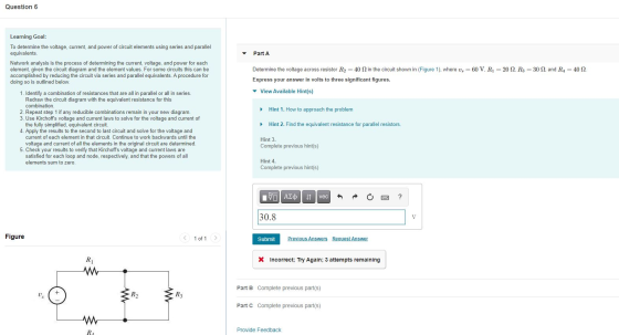
Determine the voltage across resistor R2=40ΩR2=40Ω in the circuit shown in (Figure 1), where vs=60Vvs=60V, R1=20ΩR1=20Ω, R3=30ΩR3=30Ω, and R4=40Ω
Homework Answers

Add Answer to:
Determine the voltage across resistor R2=40ΩR2=40Ω in the
circuit shown in (Figure 1), where vs=60Vvs=60V, R1=20ΩR1=20Ω,...
Determine the current through R3=50Ω in the circuit shown in (Figure 1), where vs=60V, R1=30Ω, R2=30Ω,...
 Determine the current through R3=50Ω in the circuit shown in
(Figure 1), where vs=60V, R1=30Ω, R2=30Ω, and R4=60Ω. Express your
answer in amperes to three significant figures.
I need both parts A and B please
▼ Part B Determine the current through R3-50 Ω in the circuit shown in Figure 1), where us Rs 60 S2 Express your answer in amperes to three significant figures. Review 60 V. R-30 Ω. R2 30 Ω, and Learning Goal: To determine the voltage,...
Determine the current through R3=50Ω in the circuit shown in
(Figure 1), where vs=60V, R1=30Ω, R2=30Ω, and R4=60Ω. Express your
answer in amperes to three significant figures.
I need both parts A and B please
▼ Part B Determine the current through R3-50 Ω in the circuit shown in Figure 1), where us Rs 60 S2 Express your answer in amperes to three significant figures. Review 60 V. R-30 Ω. R2 30 Ω, and Learning Goal: To determine the voltage,...
Problem 3: Determine explicitly the voltage across R3 in the circuit below R2 R1 R3 R4...
 Problem 3: Determine explicitly the voltage across R3 in the circuit below R2 R1 R3 R4 (Hint: R2 and R3 are in parallel with R1... this combination is in series with R4. The total resistance can give you the total voltage drop AND then you can just analyze as a voltage divider.)
R1 R3 R2 R4 W The circuit in the diagram contains one battery and four resistors,...
 R1 R3 R2 R4 W The circuit in the diagram contains one battery and four resistors, labeled 1 through 4. ?Which of the following is true about the way that the circuit elements are arranged Resistors 1 and 2 are in parallel while resistors 3 and 4 are in series Resistors 1 and 4 are in parallel while resistors 2 and 3 are in series Resistors 1 and 4 are in series, while resistors 2 and 3 are in parallel...
Part A. Wheatstone Bridge Circuit with a Voltage Source Vs R5 R1 R2 Vs RL R3 R4 For the circuit a...
 Part A. Wheatstone Bridge Circuit with a Voltage Source Vs R5 R1 R2 Vs RL R3 R4 For the circuit as shown below, given that R1: 23 Ω, R2° 13 O, R,-230, R4% 3 Ω. RS: 28 Ω , RL: 13 Ω ,Vs-90 . I. Wheatstone Bridge Circuit Analysis (a) Determining the load voltage VL-Vab for the Wheatstone bridge circuit with LTspice 1 Submit Answer Tries 0/3 (b) Determining the load current I following from a to b for the...
A circuit made up of 6 resistors is shown in the figure, with resistances R1 = 16 Ω, R2 = 35 Ω, R3 = 29 Ω, R4 = 73 Ω, R5 = 89 Ω, and R6 = 31 Ω.
 A circuit made up of 6 resistors is shown in the figure, with resistances R1 = 16 Ω, R2 = 35 Ω, R3 = 29 Ω, R4 = 73 Ω, R5 = 89 Ω, and R6 = 31 Ω. The total current going through the circuit is I = 11.5 A. Part (a) Express the equivalent resistance of the combination of R4, R5, and R6. Part (b) Express the equivalent resistance of the combination of R3, R4, Rs and R6. Part (c) Express...
3] Draw a circuit diagram showing resistor R1 in series with R2, and that combination in...
 3] Draw a circuit diagram showing resistor R1 in series with R2, and that combination in parallel with resistor R3 and in parallel with battery V.
Consider the electric circuit shown in the figure. Assume that the voltage of the battery is...
 Consider the electric circuit shown in the figure. Assume that
the voltage of the battery is V = 23.5 V, and the resistors are
R1 = R2 = R3 = R4 =
R5 = 2.00 Ω.
What is the equivalent resistance of the circuit?
What is the electric current flowing through resistor
R3?
Consider the electri = R4 = R5 = 2.00 2 circuit shown in the figure. Assume that the voltage of the battery is V = 23.5 V,...
Consider the electric circuit shown in the figure. Assume that
the voltage of the battery is V = 23.5 V, and the resistors are
R1 = R2 = R3 = R4 =
R5 = 2.00 Ω.
What is the equivalent resistance of the circuit?
What is the electric current flowing through resistor
R3?
Consider the electri = R4 = R5 = 2.00 2 circuit shown in the figure. Assume that the voltage of the battery is V = 23.5 V,...
Fall-18 o ot for e Figure-4 parallel connection Voltage Table-2 Data table for serics circuit e)...
 Fall-18 o ot for e Figure-4 parallel connection Voltage Table-2 Data table for serics circuit e) Repeat part e for the circuit given in figure 5 Vs Figure-5 series and parallel combination circuit Element Voltage Current Source Table-3 Data table for series and parallel combined circuit ost Lab: Q.1) Use the Kirchhoft's voltage and current laws to verify your answer in part e. Q2) Validate, using DC circuit analysis (simple series parallel equivalents) techniques, that the voltage and currents you...
For the circuit of Figure 1, choose values for resistors R1, R2, and R3
 C.la For the circuit of Figure 1, choose values for resistors R1, R2, and R3(all resistances must be greater than one Kilo ohm). Given that the voltage source Vs1 = 8V and Vs2 = 10V determine the output voltage Vout. C.1b For the same resistor values Ri, R2, and Rs you chose in part C.la Given that the voltage source Vsi = 8V and Vs2 = 10V, use Figure 2(a) to determine the output voltage Vout/ and Figure 2(b) to determine the output voltage Vout2. Discussion:...
In the circuit shown in the figure, VA = VB = 10.0 and R1 = R2...
 In the circuit shown in the figure, VA = VB = 10.0 and R1 = R2 = R3 = R4 = Rs = 50.0. Current Is flows up through Rs, and I5 = 0.0500 A. Determine the current 14 through R4. Assume the direction of positive current flow is downward through R4. mm VA 14 = A Determine the voltage V2 across R2. mm V2 = V w Determine the power P3 dissipated by R3. R P3 = W
 Determine the current through R3=50Ω in the circuit shown in
(Figure 1), where vs=60V, R1=30Ω, R2=30Ω, and R4=60Ω. Express your
answer in amperes to three significant figures.
I need both parts A and B please
▼ Part B Determine the current through R3-50 Ω in the circuit shown in Figure 1), where us Rs 60 S2 Express your answer in amperes to three significant figures. Review 60 V. R-30 Ω. R2 30 Ω, and Learning Goal: To determine the voltage,...
Determine the current through R3=50Ω in the circuit shown in
(Figure 1), where vs=60V, R1=30Ω, R2=30Ω, and R4=60Ω. Express your
answer in amperes to three significant figures.
I need both parts A and B please
▼ Part B Determine the current through R3-50 Ω in the circuit shown in Figure 1), where us Rs 60 S2 Express your answer in amperes to three significant figures. Review 60 V. R-30 Ω. R2 30 Ω, and Learning Goal: To determine the voltage,...
 Problem 3: Determine explicitly the voltage across R3 in the circuit below R2 R1 R3 R4 (Hint: R2 and R3 are in parallel with R1... this combination is in series with R4. The total resistance can give you the total voltage drop AND then you can just analyze as a voltage divider.)
 R1 R3 R2 R4 W The circuit in the diagram contains one battery and four resistors, labeled 1 through 4. ?Which of the following is true about the way that the circuit elements are arranged Resistors 1 and 2 are in parallel while resistors 3 and 4 are in series Resistors 1 and 4 are in parallel while resistors 2 and 3 are in series Resistors 1 and 4 are in series, while resistors 2 and 3 are in parallel...
 Part A. Wheatstone Bridge Circuit with a Voltage Source Vs R5 R1 R2 Vs RL R3 R4 For the circuit as shown below, given that R1: 23 Ω, R2° 13 O, R,-230, R4% 3 Ω. RS: 28 Ω , RL: 13 Ω ,Vs-90 . I. Wheatstone Bridge Circuit Analysis (a) Determining the load voltage VL-Vab for the Wheatstone bridge circuit with LTspice 1 Submit Answer Tries 0/3 (b) Determining the load current I following from a to b for the...
 3] Draw a circuit diagram showing resistor R1 in series with R2, and that combination in parallel with resistor R3 and in parallel with battery V.
 Consider the electric circuit shown in the figure. Assume that
the voltage of the battery is V = 23.5 V, and the resistors are
R1 = R2 = R3 = R4 =
R5 = 2.00 Ω.
What is the equivalent resistance of the circuit?
What is the electric current flowing through resistor
R3?
Consider the electri = R4 = R5 = 2.00 2 circuit shown in the figure. Assume that the voltage of the battery is V = 23.5 V,...
Consider the electric circuit shown in the figure. Assume that
the voltage of the battery is V = 23.5 V, and the resistors are
R1 = R2 = R3 = R4 =
R5 = 2.00 Ω.
What is the equivalent resistance of the circuit?
What is the electric current flowing through resistor
R3?
Consider the electri = R4 = R5 = 2.00 2 circuit shown in the figure. Assume that the voltage of the battery is V = 23.5 V,...
 Fall-18 o ot for e Figure-4 parallel connection Voltage Table-2 Data table for serics circuit e) Repeat part e for the circuit given in figure 5 Vs Figure-5 series and parallel combination circuit Element Voltage Current Source Table-3 Data table for series and parallel combined circuit ost Lab: Q.1) Use the Kirchhoft's voltage and current laws to verify your answer in part e. Q2) Validate, using DC circuit analysis (simple series parallel equivalents) techniques, that the voltage and currents you...
 C.la For the circuit of Figure 1, choose values for resistors R1, R2, and R3(all resistances must be greater than one Kilo ohm). Given that the voltage source Vs1 = 8V and Vs2 = 10V determine the output voltage Vout. C.1b For the same resistor values Ri, R2, and Rs you chose in part C.la Given that the voltage source Vsi = 8V and Vs2 = 10V, use Figure 2(a) to determine the output voltage Vout/ and Figure 2(b) to determine the output voltage Vout2. Discussion:...
 In the circuit shown in the figure, VA = VB = 10.0 and R1 = R2 = R3 = R4 = Rs = 50.0. Current Is flows up through Rs, and I5 = 0.0500 A. Determine the current 14 through R4. Assume the direction of positive current flow is downward through R4. mm VA 14 = A Determine the voltage V2 across R2. mm V2 = V w Determine the power P3 dissipated by R3. R P3 = W
Most questions answered within 3 hours.
-
Accent Software faces the following conditions. All of these
support Accent’s use of a market-penetration pricing...
asked 13 minutes ago -
A mathematically inclined friend emails you the following
instructions: "Meet me in the cafeteria the first...
asked 16 minutes ago -
A monopoly sells in two countries . The demand curves in the two
countries are p1...
asked 1 hour ago -
A .15kg rubber ball is bounced off a wall. Before hitting the
wall, the ball moves...
asked 1 hour ago -
A manufacturing company preparing to build a new plant is
considering three potential locations for it....
asked 1 hour ago -
B. If compound Y has approximately the same values of solubility
in toluene as compound X,...
asked 2 hours ago -
Oscar Inc. has inventory in Japan valued at 39,051,000 Yen one
year ago. One year ago...
asked 2 hours ago -
If Canada suffered from "fundamental disequilibrium," and its
government choose not to devalue its currency, a...
asked 2 hours ago -
4. How many input & output Key Value Pairs are passed into,
and emitted out of...
asked 2 hours ago -
Why would your heart not function well if constructed of
skeletal muscle? What is the particular...
asked 3 hours ago -
Please respond to this essay question in full essay form for
Chemistry 1102 Organic and Biochemistry:...
asked 3 hours ago -
Determine the head loss and velocity of flow in a water supply main
of 15.0 cm...
asked 3 hours ago