
Homework Answers


2 kN Draw the shear-force and bending-moment diagrams for the beam loaded by the 2-kN force...
 2 kN Draw the shear-force and bending-moment diagrams for the beam loaded by the 2-kN force and the 1.6 kN-m couple. State the value of the bending moment at point B. HW22-2 1.6 kN.m 0.5m 0.5 m 0.5 m
4. For the beam and loading shown, draw the shear force and bending moment diagrams and...
 4. For the beam and loading shown, draw the shear force and bending moment diagrams and determine the maximum bending and shear force and their locations. 20 KN 40 KN B D 250 mm |--2.5 m- 3m-4-2 m 80 mm 5. For the beam and loading shown, draw the shear force and bending moment diagrams and determine the maximum bending and shear force and their locations. 50 KN
Draw the shear force and bending moment diagrams for the beams shown 5 kN 3 kN/m...
 Draw the shear force and bending moment diagrams for the beams
shown
5 kN 3 kN/m 3 m 1.5 m1.5mFig. 4 3 m
Draw the shear force and bending moment diagrams for the beams
shown
5 kN 3 kN/m 3 m 1.5 m1.5mFig. 4 3 m
4. Draw shear force & bending moment diagrams for the shown beams 30 kN 20 kN...
 4. Draw shear force & bending moment diagrams for the shown beams 30 kN 20 kN IO kN m DY E 15 kN 1 kip/ft 27 kip.ft 4.5 ft
For the beams of problems 6.2-6.16, draw the shear force and bending moment diagrams and find...
 For the beams of problems 6.2-6.16, draw the shear force and
bending moment
diagrams and find the maximum shear force, maximum bending moment
and
point(s) of contraflexure (PCF).
7 kN 6 kN/m 4 kN/m B 2 m e C D E 24 kN 1,5m 7590.0.751 Figure 6.41
For the beams of problems 6.2-6.16, draw the shear force and
bending moment
diagrams and find the maximum shear force, maximum bending moment
and
point(s) of contraflexure (PCF).
7 kN 6 kN/m 4 kN/m B 2 m e C D E 24 kN 1,5m 7590.0.751 Figure 6.41
Draw the shear and moment diagrams. 2.1 kN/m A C B - 5 m - 2...
 Draw the shear and moment diagrams. 2.1 kN/m A C B - 5 m - 2 m
draw axial force, shear force and bending moment diagrams 2m 4'm 30 kN 2m 50 kN...
 draw axial force, shear force and bending moment
diagrams
2m 4'm 30 kN 2m 50 kN 4m A 3 m 1m -3m 1.5m
draw axial force, shear force and bending moment
diagrams
2m 4'm 30 kN 2m 50 kN 4m A 3 m 1m -3m 1.5m
Draw the shear and bending moment diagrams 10 kN 8 kN 15 kN m 3 m
 Draw the shear and bending moment diagrams
10 kN 8 kN 15 kN m 3 m
Draw the shear and bending moment diagrams
10 kN 8 kN 15 kN m 3 m
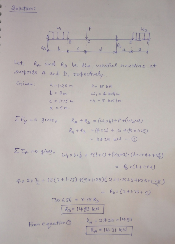
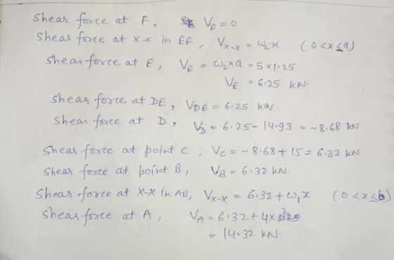
Part II: Problem 5 (15 points) Draw the shear and moment diagrams for the beam and...
 Part II: Problem 5 (15 points) Draw the shear and moment
diagrams for the beam and determine the maximum shear and the
maximum moment.
Part II: Problem 5 (15 points) Draw the shear and moment diagrams for the beam and determine the maximum shear and the maximum moment. 15 kN 5 kN/m 80 kNm B (a)
Part II: Problem 5 (15 points) Draw the shear and moment
diagrams for the beam and determine the maximum shear and the
maximum moment.
Part II: Problem 5 (15 points) Draw the shear and moment diagrams for the beam and determine the maximum shear and the maximum moment. 15 kN 5 kN/m 80 kNm B (a)
For the beam shown in Fig. 9.3, draw the shear force and bending moment diagrams. Use...
 For the beam shown in Fig. 9.3, draw the shear force and bending moment diagrams. Use the area method that relies on the relationships between loading and shear force and between shear force and bending moment. Indicate the slope of the shear force diagram at locations A, B, C, and D using the load information in Fig. 9.3. Indicate the slope of the bending moment diagram at the same four locations using information from the shear force diagram. | 6...
 2 kN Draw the shear-force and bending-moment diagrams for the beam loaded by the 2-kN force and the 1.6 kN-m couple. State the value of the bending moment at point B. HW22-2 1.6 kN.m 0.5m 0.5 m 0.5 m
 4. For the beam and loading shown, draw the shear force and bending moment diagrams and determine the maximum bending and shear force and their locations. 20 KN 40 KN B D 250 mm |--2.5 m- 3m-4-2 m 80 mm 5. For the beam and loading shown, draw the shear force and bending moment diagrams and determine the maximum bending and shear force and their locations. 50 KN
 Draw the shear force and bending moment diagrams for the beams
shown
5 kN 3 kN/m 3 m 1.5 m1.5mFig. 4 3 m
Draw the shear force and bending moment diagrams for the beams
shown
5 kN 3 kN/m 3 m 1.5 m1.5mFig. 4 3 m
 4. Draw shear force & bending moment diagrams for the shown beams 30 kN 20 kN IO kN m DY E 15 kN 1 kip/ft 27 kip.ft 4.5 ft
 For the beams of problems 6.2-6.16, draw the shear force and
bending moment
diagrams and find the maximum shear force, maximum bending moment
and
point(s) of contraflexure (PCF).
7 kN 6 kN/m 4 kN/m B 2 m e C D E 24 kN 1,5m 7590.0.751 Figure 6.41
For the beams of problems 6.2-6.16, draw the shear force and
bending moment
diagrams and find the maximum shear force, maximum bending moment
and
point(s) of contraflexure (PCF).
7 kN 6 kN/m 4 kN/m B 2 m e C D E 24 kN 1,5m 7590.0.751 Figure 6.41
 Draw the shear and moment diagrams. 2.1 kN/m A C B - 5 m - 2 m
 draw axial force, shear force and bending moment
diagrams
2m 4'm 30 kN 2m 50 kN 4m A 3 m 1m -3m 1.5m
draw axial force, shear force and bending moment
diagrams
2m 4'm 30 kN 2m 50 kN 4m A 3 m 1m -3m 1.5m
 Draw the shear and bending moment diagrams
10 kN 8 kN 15 kN m 3 m
Draw the shear and bending moment diagrams
10 kN 8 kN 15 kN m 3 m
 Part II: Problem 5 (15 points) Draw the shear and moment
diagrams for the beam and determine the maximum shear and the
maximum moment.
Part II: Problem 5 (15 points) Draw the shear and moment diagrams for the beam and determine the maximum shear and the maximum moment. 15 kN 5 kN/m 80 kNm B (a)
Part II: Problem 5 (15 points) Draw the shear and moment
diagrams for the beam and determine the maximum shear and the
maximum moment.
Part II: Problem 5 (15 points) Draw the shear and moment diagrams for the beam and determine the maximum shear and the maximum moment. 15 kN 5 kN/m 80 kNm B (a)
 For the beam shown in Fig. 9.3, draw the shear force and bending moment diagrams. Use the area method that relies on the relationships between loading and shear force and between shear force and bending moment. Indicate the slope of the shear force diagram at locations A, B, C, and D using the load information in Fig. 9.3. Indicate the slope of the bending moment diagram at the same four locations using information from the shear force diagram. | 6...
Most questions answered within 3 hours.
-
Derive the long wavelength limit of the Planck energy density
distribution
asked 13 minutes ago -
Phosphorous + bromine = phosphorous tribromide. If 35.0 g of
bromine are reacted and 27.9 grams...
asked 23 minutes ago -
Calculate the pH of each of the following solutions.
0.50 M HBr
3.1×10⁻⁴ M KOH
4.2×10⁻⁵...
asked 3 hours ago -
For the year ended December 31, Depot Max’s cost of merchandise
sold was $85,600. Inventory at the...
asked 3 hours ago -
Week 10 - Professional Memo Assignment
Professional Memo Assignment
Your mission for this week, should you...
asked 3 hours ago -
Write a Python program that stores the data for each
player on the team, and it...
asked 4 hours ago -
In
the last 3 months, mike never knows when he is going to get his
allowance...
asked 4 hours ago -
Is Ca(OH)2 a Bronsted base, Lewis base, or both? Why?
asked 4 hours ago -
1A- Why don’t voters complain about U.S. tariffs on imported
sugar?
Because sugar is only a...
asked 4 hours ago -
Cash Payback Period
Primera Banco is evaluating two capital investment proposals for
a drive-up ATM kiosk,...
asked 4 hours ago -
Create a button in Swift (Xcode) that will create a charge,
create a charge using Stripe's...
asked 4 hours ago -
The reaction rate of CO and NO2 in the reaction
CO(g) + NO2(g) → CO2(g) +...
asked 4 hours ago