
Homework Answers

Add Answer to:
Problem 3: (25%) The steel frame shown in the Figure is subjected to a force P(t)...
Questions 5-8 A steel frame shown below is subjected to combined uniformly distributed gravity load (w...
 Questions 5-8
A steel frame shown below is subjected to combined uniformly distributed gravity load (w 2 kips/f) and a horizontal earthquake load of H-10 kips Both the beams and the columns are made of W12x120 section having a yield strength of F 45 ksi. The Young's modulus of steel s E-29,000 ksi. The distributed load w is used to simulate the self-weight of the beam, the load transferred from roof slab, as well addition superimposed dead loads. The self-weigh...
Questions 5-8
A steel frame shown below is subjected to combined uniformly distributed gravity load (w 2 kips/f) and a horizontal earthquake load of H-10 kips Both the beams and the columns are made of W12x120 section having a yield strength of F 45 ksi. The Young's modulus of steel s E-29,000 ksi. The distributed load w is used to simulate the self-weight of the beam, the load transferred from roof slab, as well addition superimposed dead loads. The self-weigh...
9. For the frame shown below, the stiffness of fixed column is 12El/L3 and for the...
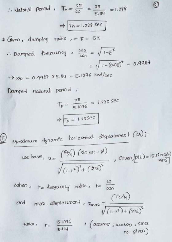
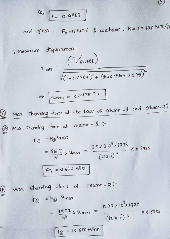
 9. For the frame shown below, the stiffness of fixed column is 12El/L3 and for the pinned is 3EI/L, I for W 8 x 24 82.8 in4, I for W 10x 33 170 in, E-29,000 ksi. Find: (2 Points each subsection) (i) Total Stiffness. (i) Natural Frequency in rad/sec. and Hz, and Period. i) Assuming the damping is negligible, find displacement, velocity and acceleration at t 5 sec. using initial conditions yo 0.75 inch and vo 20 inch/sec. How much...
The frame below has wind load and dead as shown. Use w(Dead) = 6 kip/ft and...
 The frame below has wind load and dead as shown. Use w(Dead) = 6
kip/ft and w(Live) = 3 kip/ft, L = 30 ft and H = 15 ft. The beams
and columns have modulus of elasticity E of 29000 ksi and moment of
inertias I(beam) = 2000 in4 and I(column) = 800
in4. Similarly they have cross-sectional areas A(beam) =
20 in2 and A(column) = 25 in2. Consider that
the wind can act in both horizontal directions.
Determine:
The...
The frame below has wind load and dead as shown. Use w(Dead) = 6
kip/ft and w(Live) = 3 kip/ft, L = 30 ft and H = 15 ft. The beams
and columns have modulus of elasticity E of 29000 ksi and moment of
inertias I(beam) = 2000 in4 and I(column) = 800
in4. Similarly they have cross-sectional areas A(beam) =
20 in2 and A(column) = 25 in2. Consider that
the wind can act in both horizontal directions.
Determine:
The...
Problem 22. Two-story, one-bay unbraced frame shown below is subjected to gravitational dead and live loads...
 Problem 22. Two-story, one-bay unbraced frame shown below is subjected to gravitational dead and live loads and wind lateral load. The columns are made of W18x65 (I,-1070 in , Ag- 19.1 in2, r-7.49 in, ry-1.69 in) and beams are made of W18x71 (1, 1170 in). The table below shows the moments at the ends of column 4-5 due to three load cases. The frame is fully braced in lateral direction. Use Grade50 steel Bending is about strong axis. All gravity...
1.100 kips Problem 5: The frame with the factored loads in 10 kips Figure 5 is fixed at the base....
 1.100 kips Problem 5: The frame with the factored loads in 10 kips Figure 5 is fixed at the base. The columns are oriented so that in-plane bending will be about the x-axis. The columns are continuously braced in the transverse direction such that they can only buckle in-plane. Use A992 steel and select the lightest W14 for the column. The beam size is W24x76 15 f 20 ft
1.100 kips Problem 5: The frame with the factored loads in...
1.100 kips Problem 5: The frame with the factored loads in 10 kips Figure 5 is fixed at the base. The columns are oriented so that in-plane bending will be about the x-axis. The columns are continuously braced in the transverse direction such that they can only buckle in-plane. Use A992 steel and select the lightest W14 for the column. The beam size is W24x76 15 f 20 ft
1.100 kips Problem 5: The frame with the factored loads in...
Chapter 15, Supplemental Question 152 A 2.5-in.-diameter solid aluminum post is subjected to a horizontal force of Px = 8.8 kips, a vertical force of Py = 19.3 kips, and a concentrated torque of T = 4...
 Chapter 15, Supplemental
Question 152 A 2.5-in.-diameter solid aluminum post is subjected to
a horizontal force of Px = 8.8 kips, a vertical force of Py = 19.3
kips, and a concentrated torque of T = 4.2 kip-ft, acting in the
directions shown. Assume L = 3 in. The yield strength of the
aluminum is 49 ksi, and a minimum factor of safety of FSmin = 1.67
is required by specification. Consider points H and K, and
determine whether the...
Chapter 15, Supplemental
Question 152 A 2.5-in.-diameter solid aluminum post is subjected to
a horizontal force of Px = 8.8 kips, a vertical force of Py = 19.3
kips, and a concentrated torque of T = 4.2 kip-ft, acting in the
directions shown. Assume L = 3 in. The yield strength of the
aluminum is 49 ksi, and a minimum factor of safety of FSmin = 1.67
is required by specification. Consider points H and K, and
determine whether the...
Problem 6 (15 pts) The beam shown is subjected to a vertical shear force of 42 kips and is fabric...
 Problem 6 (15 pts) The beam shown is subjected to a vertical shear force of 42 kips and is fabricated by fastening the C12 x 25 and S20 x 86 rolled steel members with pairs of 0.5 in. diameter bolts as shown. The allowable shear stress of a bolt is 45 ksi. Determine the maximum spacing. C channel ycg- Iz- Bolt Spacing, MAX
Problem 6 (15 pts) The beam shown is subjected to a vertical shear force of 42 kips...
Problem 6 (15 pts) The beam shown is subjected to a vertical shear force of 42 kips and is fabricated by fastening the C12 x 25 and S20 x 86 rolled steel members with pairs of 0.5 in. diameter bolts as shown. The allowable shear stress of a bolt is 45 ksi. Determine the maximum spacing. C channel ycg- Iz- Bolt Spacing, MAX
Problem 6 (15 pts) The beam shown is subjected to a vertical shear force of 42 kips...
The single-story unbraced frame shown below is subjected to dead load, roof live load, and wind load Figure 1 shows the...
 The single-story unbraced frame shown below is subjected to dead load, roof live load, and wind load Figure 1 shows the results of a first-order analysis relative to the columns of the frame. The axial load and end moment (also equal to the maximum moment in the column) are given separately for the different load cases (i.e., dead load, roof live load, and lateral wind load). All vertical loads are symmetrically placed and contribute only to the Mnt moments (i.e.,...
14.23- TOPIC: COLUMNS together, as shown in figure below. The applied load is P -80 kips....
 14.23- TOPIC: COLUMNS together, as shown in figure below. The applied load is P -80 kips. a) If the length is L- 10 ft, what are the maximum stress and the maximum deflection? Consider this: A wooden box column (E- 1800 ksi) is constructed by joining four pieces of lumber b) If the allowable stress is 3 ksi, what is the maximum permissible length L to the nearest inch? Present a clearly written step-by-step solution 4 in 4 in 8...
i need clear and right solution pleaee. pleaes A steel plate of (0.5 in thickness) shown in the figure was fixed by four bolts of (0.5*13-UNC grade 4) to the vertical steel column of (0.6 in thick...
 i need clear and right solution pleaee.
pleaes
A steel plate of (0.5 in thickness) shown in the figure was fixed by four bolts of (0.5*13-UNC grade 4) to the vertical steel column of (0.6 in thickness) as shown in figure below. An inclined eccentric force F of 10 kips was subjected to the plate at point A. Calculate: (a) The maximum stress in the rivets. (b) Check the safety factor if the plate and wall have a tensile strength...
i need clear and right solution pleaee.
pleaes
A steel plate of (0.5 in thickness) shown in the figure was fixed by four bolts of (0.5*13-UNC grade 4) to the vertical steel column of (0.6 in thickness) as shown in figure below. An inclined eccentric force F of 10 kips was subjected to the plate at point A. Calculate: (a) The maximum stress in the rivets. (b) Check the safety factor if the plate and wall have a tensile strength...
 Questions 5-8
A steel frame shown below is subjected to combined uniformly distributed gravity load (w 2 kips/f) and a horizontal earthquake load of H-10 kips Both the beams and the columns are made of W12x120 section having a yield strength of F 45 ksi. The Young's modulus of steel s E-29,000 ksi. The distributed load w is used to simulate the self-weight of the beam, the load transferred from roof slab, as well addition superimposed dead loads. The self-weigh...
Questions 5-8
A steel frame shown below is subjected to combined uniformly distributed gravity load (w 2 kips/f) and a horizontal earthquake load of H-10 kips Both the beams and the columns are made of W12x120 section having a yield strength of F 45 ksi. The Young's modulus of steel s E-29,000 ksi. The distributed load w is used to simulate the self-weight of the beam, the load transferred from roof slab, as well addition superimposed dead loads. The self-weigh...
 9. For the frame shown below, the stiffness of fixed column is 12El/L3 and for the pinned is 3EI/L, I for W 8 x 24 82.8 in4, I for W 10x 33 170 in, E-29,000 ksi. Find: (2 Points each subsection) (i) Total Stiffness. (i) Natural Frequency in rad/sec. and Hz, and Period. i) Assuming the damping is negligible, find displacement, velocity and acceleration at t 5 sec. using initial conditions yo 0.75 inch and vo 20 inch/sec. How much...
 The frame below has wind load and dead as shown. Use w(Dead) = 6
kip/ft and w(Live) = 3 kip/ft, L = 30 ft and H = 15 ft. The beams
and columns have modulus of elasticity E of 29000 ksi and moment of
inertias I(beam) = 2000 in4 and I(column) = 800
in4. Similarly they have cross-sectional areas A(beam) =
20 in2 and A(column) = 25 in2. Consider that
the wind can act in both horizontal directions.
Determine:
The...
The frame below has wind load and dead as shown. Use w(Dead) = 6
kip/ft and w(Live) = 3 kip/ft, L = 30 ft and H = 15 ft. The beams
and columns have modulus of elasticity E of 29000 ksi and moment of
inertias I(beam) = 2000 in4 and I(column) = 800
in4. Similarly they have cross-sectional areas A(beam) =
20 in2 and A(column) = 25 in2. Consider that
the wind can act in both horizontal directions.
Determine:
The...
 Problem 22. Two-story, one-bay unbraced frame shown below is subjected to gravitational dead and live loads and wind lateral load. The columns are made of W18x65 (I,-1070 in , Ag- 19.1 in2, r-7.49 in, ry-1.69 in) and beams are made of W18x71 (1, 1170 in). The table below shows the moments at the ends of column 4-5 due to three load cases. The frame is fully braced in lateral direction. Use Grade50 steel Bending is about strong axis. All gravity...
 1.100 kips Problem 5: The frame with the factored loads in 10 kips Figure 5 is fixed at the base. The columns are oriented so that in-plane bending will be about the x-axis. The columns are continuously braced in the transverse direction such that they can only buckle in-plane. Use A992 steel and select the lightest W14 for the column. The beam size is W24x76 15 f 20 ft
1.100 kips Problem 5: The frame with the factored loads in...
1.100 kips Problem 5: The frame with the factored loads in 10 kips Figure 5 is fixed at the base. The columns are oriented so that in-plane bending will be about the x-axis. The columns are continuously braced in the transverse direction such that they can only buckle in-plane. Use A992 steel and select the lightest W14 for the column. The beam size is W24x76 15 f 20 ft
1.100 kips Problem 5: The frame with the factored loads in...
 Chapter 15, Supplemental
Question 152 A 2.5-in.-diameter solid aluminum post is subjected to
a horizontal force of Px = 8.8 kips, a vertical force of Py = 19.3
kips, and a concentrated torque of T = 4.2 kip-ft, acting in the
directions shown. Assume L = 3 in. The yield strength of the
aluminum is 49 ksi, and a minimum factor of safety of FSmin = 1.67
is required by specification. Consider points H and K, and
determine whether the...
Chapter 15, Supplemental
Question 152 A 2.5-in.-diameter solid aluminum post is subjected to
a horizontal force of Px = 8.8 kips, a vertical force of Py = 19.3
kips, and a concentrated torque of T = 4.2 kip-ft, acting in the
directions shown. Assume L = 3 in. The yield strength of the
aluminum is 49 ksi, and a minimum factor of safety of FSmin = 1.67
is required by specification. Consider points H and K, and
determine whether the...
 Problem 6 (15 pts) The beam shown is subjected to a vertical shear force of 42 kips and is fabricated by fastening the C12 x 25 and S20 x 86 rolled steel members with pairs of 0.5 in. diameter bolts as shown. The allowable shear stress of a bolt is 45 ksi. Determine the maximum spacing. C channel ycg- Iz- Bolt Spacing, MAX
Problem 6 (15 pts) The beam shown is subjected to a vertical shear force of 42 kips...
Problem 6 (15 pts) The beam shown is subjected to a vertical shear force of 42 kips and is fabricated by fastening the C12 x 25 and S20 x 86 rolled steel members with pairs of 0.5 in. diameter bolts as shown. The allowable shear stress of a bolt is 45 ksi. Determine the maximum spacing. C channel ycg- Iz- Bolt Spacing, MAX
Problem 6 (15 pts) The beam shown is subjected to a vertical shear force of 42 kips...
 The single-story unbraced frame shown below is subjected to dead load, roof live load, and wind load Figure 1 shows the results of a first-order analysis relative to the columns of the frame. The axial load and end moment (also equal to the maximum moment in the column) are given separately for the different load cases (i.e., dead load, roof live load, and lateral wind load). All vertical loads are symmetrically placed and contribute only to the Mnt moments (i.e.,...
 14.23- TOPIC: COLUMNS together, as shown in figure below. The applied load is P -80 kips. a) If the length is L- 10 ft, what are the maximum stress and the maximum deflection? Consider this: A wooden box column (E- 1800 ksi) is constructed by joining four pieces of lumber b) If the allowable stress is 3 ksi, what is the maximum permissible length L to the nearest inch? Present a clearly written step-by-step solution 4 in 4 in 8...
 i need clear and right solution pleaee.
pleaes
A steel plate of (0.5 in thickness) shown in the figure was fixed by four bolts of (0.5*13-UNC grade 4) to the vertical steel column of (0.6 in thickness) as shown in figure below. An inclined eccentric force F of 10 kips was subjected to the plate at point A. Calculate: (a) The maximum stress in the rivets. (b) Check the safety factor if the plate and wall have a tensile strength...
i need clear and right solution pleaee.
pleaes
A steel plate of (0.5 in thickness) shown in the figure was fixed by four bolts of (0.5*13-UNC grade 4) to the vertical steel column of (0.6 in thickness) as shown in figure below. An inclined eccentric force F of 10 kips was subjected to the plate at point A. Calculate: (a) The maximum stress in the rivets. (b) Check the safety factor if the plate and wall have a tensile strength...
Most questions answered within 3 hours.
-
which of the following may lead to speciation?
a. a group of individuals from a mainland...
asked 4 minutes ago -
Please I need today answer for This question and it is very
important and I need...
asked 22 minutes ago -
Five years from today, you plan to invest $3,700 for 7
additional years at 5.8 percent...
asked 22 minutes ago -
GDL just paid a dividend of $4.06 per share. You expect
dividends to grow 12% for...
asked 24 minutes ago -
which of the following is a basic compound?
vinegar
orange juice
seltzer
none of the above
asked 27 minutes ago -
5. Suppose you obtained 0.55 g of crude clove oil from 7.0 g of
fresh cloves....
asked 37 minutes ago -
Provide a paragraph of introduction that generally describes
cognitive development over the lifespan.
asked 42 minutes ago -
In a market, when the price increased the total expenditure on
the good also increased. Is...
asked 41 minutes ago -
If 5.70 g of potassium react with water, how many grams of
hydrogen gas, H2, are...
asked 55 minutes ago -
How many moles of CO2 and H2O will be
produced by combustion analysis of 0.010 mol...
asked 54 minutes ago -
Tennis champion Maria Sharapova is capable of serving a tennis
ball at 126 mph.
b) What...
asked 1 hour ago -
The electric potential V in the space between the plates of a
given vacuum tube is...
asked 1 hour ago