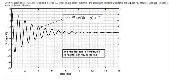
Given the second-order transient response of a series RLC circuit (shown below), determine the attenuation constant 'α' using the plot. Express your answer in Volts/sec. Round your answer to the nearest integer.
Homework Answers

Add Answer to:
Given the second-order transient response of a series RLC
circuit (shown below), determine the attenuation constant...
Given that damped frequency is β = 4 rad/sec and attenuation constant is α = 3 volts/sec, determine...
Given that damped frequency is β = 4 rad/sec and attenuation constant is α = 3 volts/sec, determine the resonant frequency ω0 in radians/sec. Round your answer to the nearest integer.
Circuit 1 Transient response of a series RLC circuit The two switches in the circuit in...
 Circuit 1 Transient response of a series RLC circuit The two switches in the circuit in Figure 8 operate synchronously. When switch 1 is in position "a", switch 2 is closed. When switch 1 is in position "b", switch 2 is open. Switch 1 has been in position "a" for a very long time. At 1-0, it moves instantaneously to position 4Ω t=0 2 8Ω 100mH 150V| 2Ω 60 V Figure 8: Circuit for Tasks 3 and 4 TASK 3...
The resonant frequency (ω0) of series RLC circuit is 44.721 kilo-rad/sec and the damped oscillation frequency,...
The resonant frequency (ω0) of series RLC circuit is 44.721 kilo-rad/sec and the damped oscillation frequency, (β) of the same circuit is 33.166 kilo-rad/sec. Determine the value of resistor used in this circuit. The inductor used has a value of 50mH and capacitor used is 0.01 µF. Express answer in kilo-ohms. Round to the nearest integer.
A second-order RLC circuit is shown in Fig. 1 0.05F 3Ω 2Ω 6A 6A 5H Fig.1 A second-order RLC cir...
 A second-order RLC circuit is shown in Fig. 1 0.05F 3Ω 2Ω 6A 6A 5H Fig.1 A second-order RLC circuit with a switch (1) Analytical part: derive the differential equations and solve them to find the response i(t for t>0. Specify whether it is an underdamped, critically damped or overdamped case.
A second-order RLC circuit is shown in Fig. 1
0.05F 3Ω 2Ω 6A 6A 5H Fig.1 A second-order RLC circuit with a switch (1) Analytical part: derive the differential...
A second-order RLC circuit is shown in Fig. 1 0.05F 3Ω 2Ω 6A 6A 5H Fig.1 A second-order RLC circuit with a switch (1) Analytical part: derive the differential equations and solve them to find the response i(t for t>0. Specify whether it is an underdamped, critically damped or overdamped case.
A second-order RLC circuit is shown in Fig. 1
0.05F 3Ω 2Ω 6A 6A 5H Fig.1 A second-order RLC circuit with a switch (1) Analytical part: derive the differential...
10. Given a series RLC circuit (below) with a0-1 rad/s, Q = 12. a. Calculate the...
 10. Given a series RLC circuit (below) with a0-1 rad/s, Q = 12. a. Calculate the zero-input response of the circuit (Uy is the output). Express your answer in terms of i (0) and vc (0). b. Find the impulse response by writing and solving the circuit differential equation. c. Intuitively, what are the values of i, (0+), and i,'(0+)? R C
Question One (a) The Impulse Response of a second order system is given by h(t) where: h(t) 4000e...
 Question One (a) The Impulse Response of a second order system is given by h(t) where: h(t) 4000e 3000 c0, where the time, t, is given in milliseconds (ms) and h(t) is considered to be the resulting voltage in volts. 0) Derive the Transfer Function, the Laplace Transform H(s) of h(t). () Using part (0). write out the Frequency Response, HGo), of the second order (ii) Express the Frequency Response obtained in part (i) as a single response system. and...
3. (40 pts total) Eigenvalues of Systems of Equations Application: Series RLC Circuit, Natural, or Transient...
 3. (40 pts total) Eigenvalues of Systems of Equations Application: Series RLC Circuit, Natural, or Transient Response (Remember EE280, maybe not) M SR v(t) Consider a series RLC circuit, with a resistor R, inductor L, and capacitor C in series. The same current i(t) flows through R, L, and C. The switch S1 is initially closed and S2 is initially open allowing the circuit to fully charge. At t=0 the switch S1 opens and S2 closes as shown above. Solving...
Problem 2 Obtain the second-order ODE describing the capacitor voltage v(t) in the series RLC circuit...
 Problem 2 Obtain the second-order ODE describing the capacitor voltage v(t) in the series RLC circuit shown below. Hint: Confer with Problem 3.14 in the textbook and use i()for the loop current. 1S2 1 H v(t) (t 2F)
Solve all the problems shown below Problem 1 In a source free RLC series circuit If...
 Solve all the problems shown below Problem 1 In a source free RLC series circuit If R=1092 ,L=5H ,and C= 2 mF 1) Find a.,0, and the characteristics roots $,$2. 2) Find the response i(t) knowing that v(0)=5V and i(0)=1A Problem 2 In a source free RLC parallel circuit If R=52 ,L= 1H ,and C= 10 m 1) Find a ,0, and the characteristics roots S1,S2. 2) Find the response V(t) knowing that v(O)=10V and i(0)=5A Problem 3 In a...
Question One (a) The Impulse Response of a second order system is given by h(t) where: h (t) 4000...
 Question One (a) The Impulse Response of a second order system is given by h(t) where: h (t) 4000 e 3000 e20 where the time, t, is given in milliseconds (ms) and h(t) is considered to be the resulting voltage in volts. (0) Derive the Transfer Function, the Laplace Transform H(s) of h(t). (i) Using part (0, write out the Frequency Response, H(jo), of the second order (ii) Express the Frequency Response obtained in part (i) as a single response...
 Circuit 1 Transient response of a series RLC circuit The two switches in the circuit in Figure 8 operate synchronously. When switch 1 is in position "a", switch 2 is closed. When switch 1 is in position "b", switch 2 is open. Switch 1 has been in position "a" for a very long time. At 1-0, it moves instantaneously to position 4Ω t=0 2 8Ω 100mH 150V| 2Ω 60 V Figure 8: Circuit for Tasks 3 and 4 TASK 3...
 A second-order RLC circuit is shown in Fig. 1 0.05F 3Ω 2Ω 6A 6A 5H Fig.1 A second-order RLC circuit with a switch (1) Analytical part: derive the differential equations and solve them to find the response i(t for t>0. Specify whether it is an underdamped, critically damped or overdamped case.
A second-order RLC circuit is shown in Fig. 1
0.05F 3Ω 2Ω 6A 6A 5H Fig.1 A second-order RLC circuit with a switch (1) Analytical part: derive the differential...
A second-order RLC circuit is shown in Fig. 1 0.05F 3Ω 2Ω 6A 6A 5H Fig.1 A second-order RLC circuit with a switch (1) Analytical part: derive the differential equations and solve them to find the response i(t for t>0. Specify whether it is an underdamped, critically damped or overdamped case.
A second-order RLC circuit is shown in Fig. 1
0.05F 3Ω 2Ω 6A 6A 5H Fig.1 A second-order RLC circuit with a switch (1) Analytical part: derive the differential...
 10. Given a series RLC circuit (below) with a0-1 rad/s, Q = 12. a. Calculate the zero-input response of the circuit (Uy is the output). Express your answer in terms of i (0) and vc (0). b. Find the impulse response by writing and solving the circuit differential equation. c. Intuitively, what are the values of i, (0+), and i,'(0+)? R C
 Question One (a) The Impulse Response of a second order system is given by h(t) where: h(t) 4000e 3000 c0, where the time, t, is given in milliseconds (ms) and h(t) is considered to be the resulting voltage in volts. 0) Derive the Transfer Function, the Laplace Transform H(s) of h(t). () Using part (0). write out the Frequency Response, HGo), of the second order (ii) Express the Frequency Response obtained in part (i) as a single response system. and...
 3. (40 pts total) Eigenvalues of Systems of Equations Application: Series RLC Circuit, Natural, or Transient Response (Remember EE280, maybe not) M SR v(t) Consider a series RLC circuit, with a resistor R, inductor L, and capacitor C in series. The same current i(t) flows through R, L, and C. The switch S1 is initially closed and S2 is initially open allowing the circuit to fully charge. At t=0 the switch S1 opens and S2 closes as shown above. Solving...
 Problem 2 Obtain the second-order ODE describing the capacitor voltage v(t) in the series RLC circuit shown below. Hint: Confer with Problem 3.14 in the textbook and use i()for the loop current. 1S2 1 H v(t) (t 2F)
 Solve all the problems shown below Problem 1 In a source free RLC series circuit If R=1092 ,L=5H ,and C= 2 mF 1) Find a.,0, and the characteristics roots $,$2. 2) Find the response i(t) knowing that v(0)=5V and i(0)=1A Problem 2 In a source free RLC parallel circuit If R=52 ,L= 1H ,and C= 10 m 1) Find a ,0, and the characteristics roots S1,S2. 2) Find the response V(t) knowing that v(O)=10V and i(0)=5A Problem 3 In a...
 Question One (a) The Impulse Response of a second order system is given by h(t) where: h (t) 4000 e 3000 e20 where the time, t, is given in milliseconds (ms) and h(t) is considered to be the resulting voltage in volts. (0) Derive the Transfer Function, the Laplace Transform H(s) of h(t). (i) Using part (0, write out the Frequency Response, H(jo), of the second order (ii) Express the Frequency Response obtained in part (i) as a single response...
Most questions answered within 3 hours.
-
(a) A piston at 6.1 atm contains a gas that occupies a volume of
3.5 L....
asked 59 minutes ago -
Please answer true or false. Words
cannot be changed or added in to make it true...
asked 58 minutes ago -
An empty test tube weighs 15.923 grams. Then,
MgCl2•6H2O is added into the test tube. After...
asked 1 hour ago -
Assume memory access is 10 units of time and disk access is
10000 units of time....
asked 1 hour ago -
1. Are all good samples random?
2. Magazines often report surveys giving statistics such as “63%...
asked 1 hour ago -
Under all the various types of market structures, firms
must eventually earn some economic profits for...
asked 1 hour ago -
Consider the following fitness regime for a single locus trait
with two co-dominant alleles: w11 =...
asked 1 hour ago -
A large cable company reports the following.
80% of its customers subscribe to its cable TV...
asked 1 hour ago -
Please answer the question in brief.
Discuss the role of ERP in organizations. Are ERP tools...
asked 1 hour ago -
Discuss the pros and cons of collaborative software such
as SameTime. Does it increase productivity? What...
asked 1 hour ago -
Buying your in-laws a gift because it’s expected is
due to the ____________ motive of gift-giving....
asked 1 hour ago -
Calculate the expected value, the variance, and the standard
deviation of the given random variable X....
asked 2 hours ago