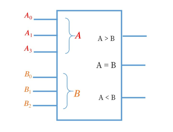
1. Implement a circuit for the chip diagram, write the truth table, write the equations, and the simplified circuit diagram using AND and OR gates.
1. Implement a circuit for the chip diagram, write the truth table,
write the equations, and the simplified circuit diagram using AND
and OR gates.
Homework Answers


Add Answer to:
1. Implement a circuit for the chip diagram, write the
truth table, write the equations, and...
Create a truth table to implement AND logic using only NAND gates. Draw the circuit diagram...
Create a truth table to implement AND logic using only NAND gates. Draw the circuit diagram (schematic) for the implementation. Do the same for OR logic using only NOR gates.
Draw the circuit diagram for the following truth table: These are the outputs from the circuit...
 Draw the circuit diagram for the following truth table: These are the outputs from the circuit X Y These are the inputs to the circuit B C 0 0 1 0 0 0 0 1 D 0 1 0 1 1 1 You are only permitted to use AND, OR and NOT gates.
Q6. a) Write the output expression for the circuit shown in the figure. b) Develop truth...
 Q6. a) Write the output expression for the circuit shown in the figure. b) Develop truth table for the circuit. (1 Mark) (4 Marks) A B C 13 X D Fig.2 07 [5] a) Minimize the following logic function using K-Map. b) Implement the minimized expression using basic gates. (3 Marks) (2 Marks) F(A,B,C,D) = (0,2,5,7,8,10,13,15) Q8 a) Write the output expression of the logic circuit shown in the figure. b) Minimize the expression using Boolean laws and theorems. C)...
Write the equation of the following truth table and construct the corresponding circuit using AND, OR...
 Write the equation of the following truth table and construct the corresponding circuit using AND, OR and NOT gates: A B COutput 0 0 0 1 1 0 1 1 10 10 10 1 0 11 1 110 1
Using the Boolean logic expression below, draw circuit diagram with logic gates that will implement your...
 Using the Boolean logic expression below, draw circuit diagram with logic gates that will implement your Boolean expression without simplifying or expanding the expression. F(A, B, C, D) = ABD + ABCD + ABCD + ABCD Complete a Truth Table F(A, B, C, D). Use your logic circuit diagram and Boolean logic expression as much as possible.
3) Write the Boolean Expression for function Z as defined by the following Truth Table in...
 3) Write the Boolean Expression for function Z as defined by the following Truth Table in both canonical and simplified forms. Implement function Z using a NOT-AND-OR network. (Please, use straight lines for connections. Use shaded areas to neatly draw your gates.) Z 888 ABC 000 001 010 011 100 101 110 III Z (from Table) - Z (simplified) =
Can I get help here ??? its digital circuit electrical engineering questions P4. 20pts For the...
 Can I get help here ??? its digital circuit electrical
engineering questions
P4. 20pts For the timing diagram in Figure P2.3, writhe the truth table and synthesize the function f(x, х, Х,). 1 0 0 Time Figure P2.3 P5. 30pts Given the Boolean function, F = xy'z + x'y'z + xyz (a) List the truth table of the function (b) Implement the logic gate circuit using the original Boolean expression (c) Simplify the algebraic expression using Boolean algebra (d) List...
Can I get help here ??? its digital circuit electrical
engineering questions
P4. 20pts For the timing diagram in Figure P2.3, writhe the truth table and synthesize the function f(x, х, Х,). 1 0 0 Time Figure P2.3 P5. 30pts Given the Boolean function, F = xy'z + x'y'z + xyz (a) List the truth table of the function (b) Implement the logic gate circuit using the original Boolean expression (c) Simplify the algebraic expression using Boolean algebra (d) List...
after completing the truth table, write equations for each output segment. ( through Sa-Sg so 7...
 after completing the truth table, write equations for each output
segment. ( through Sa-Sg so 7 equations) using k-maps
next translate your equations into logic gates using
only ONE design for all the equations.
7-segment 4, display7 decoder S Figure 3.7-segment display decoder To design your seven-segment display decoder, you will first write the truth table specifying the output values for each input combination. We have started the truth table for you in Table 1. For example, when the input...
after completing the truth table, write equations for each output
segment. ( through Sa-Sg so 7 equations) using k-maps
next translate your equations into logic gates using
only ONE design for all the equations.
7-segment 4, display7 decoder S Figure 3.7-segment display decoder To design your seven-segment display decoder, you will first write the truth table specifying the output values for each input combination. We have started the truth table for you in Table 1. For example, when the input...
A combination circuit is specified by the following Boolean functions listed below. h(a, b, c) = b,c' + a'c Implement the circuit with a 3x8 decoder. Provide truth table and drawing the l...
 A combination circuit is specified by the following Boolean functions listed below. h(a, b, c) = b,c' + a'c Implement the circuit with a 3x8 decoder. Provide truth table and drawing the logic/circuit diagram. Use the block diagram for the decoder provided in Figure A4 in supplements. Please label the inputs and outputs clearly. Note: use single 3x8 decoder Question 2 (15 points] A priority encoder is an encoder circuit that includes the Truth Table of a priority function. The...
1. write a truth table using this symbol: --> 2. write the inputs for the truth...
1. write a truth table using this symbol: --> 2. write the inputs for the truth table to the left of the --> and write the outputs for the truth table to the right of the --> 3. write the compliment, or NOT using ' As an example: The truth table for AND is written this way: A B --> A AND B 0 0 --> 0 0 1 --> 0 1 0 --> 0 1 1 --> 1 or...
 Draw the circuit diagram for the following truth table: These are the outputs from the circuit X Y These are the inputs to the circuit B C 0 0 1 0 0 0 0 1 D 0 1 0 1 1 1 You are only permitted to use AND, OR and NOT gates.
 Q6. a) Write the output expression for the circuit shown in the figure. b) Develop truth table for the circuit. (1 Mark) (4 Marks) A B C 13 X D Fig.2 07 [5] a) Minimize the following logic function using K-Map. b) Implement the minimized expression using basic gates. (3 Marks) (2 Marks) F(A,B,C,D) = (0,2,5,7,8,10,13,15) Q8 a) Write the output expression of the logic circuit shown in the figure. b) Minimize the expression using Boolean laws and theorems. C)...
 Write the equation of the following truth table and construct the corresponding circuit using AND, OR and NOT gates: A B COutput 0 0 0 1 1 0 1 1 10 10 10 1 0 11 1 110 1
 Using the Boolean logic expression below, draw circuit diagram with logic gates that will implement your Boolean expression without simplifying or expanding the expression. F(A, B, C, D) = ABD + ABCD + ABCD + ABCD Complete a Truth Table F(A, B, C, D). Use your logic circuit diagram and Boolean logic expression as much as possible.
 3) Write the Boolean Expression for function Z as defined by the following Truth Table in both canonical and simplified forms. Implement function Z using a NOT-AND-OR network. (Please, use straight lines for connections. Use shaded areas to neatly draw your gates.) Z 888 ABC 000 001 010 011 100 101 110 III Z (from Table) - Z (simplified) =
 Can I get help here ??? its digital circuit electrical
engineering questions
P4. 20pts For the timing diagram in Figure P2.3, writhe the truth table and synthesize the function f(x, х, Х,). 1 0 0 Time Figure P2.3 P5. 30pts Given the Boolean function, F = xy'z + x'y'z + xyz (a) List the truth table of the function (b) Implement the logic gate circuit using the original Boolean expression (c) Simplify the algebraic expression using Boolean algebra (d) List...
Can I get help here ??? its digital circuit electrical
engineering questions
P4. 20pts For the timing diagram in Figure P2.3, writhe the truth table and synthesize the function f(x, х, Х,). 1 0 0 Time Figure P2.3 P5. 30pts Given the Boolean function, F = xy'z + x'y'z + xyz (a) List the truth table of the function (b) Implement the logic gate circuit using the original Boolean expression (c) Simplify the algebraic expression using Boolean algebra (d) List...
 after completing the truth table, write equations for each output
segment. ( through Sa-Sg so 7 equations) using k-maps
next translate your equations into logic gates using
only ONE design for all the equations.
7-segment 4, display7 decoder S Figure 3.7-segment display decoder To design your seven-segment display decoder, you will first write the truth table specifying the output values for each input combination. We have started the truth table for you in Table 1. For example, when the input...
after completing the truth table, write equations for each output
segment. ( through Sa-Sg so 7 equations) using k-maps
next translate your equations into logic gates using
only ONE design for all the equations.
7-segment 4, display7 decoder S Figure 3.7-segment display decoder To design your seven-segment display decoder, you will first write the truth table specifying the output values for each input combination. We have started the truth table for you in Table 1. For example, when the input...
 A combination circuit is specified by the following Boolean functions listed below. h(a, b, c) = b,c' + a'c Implement the circuit with a 3x8 decoder. Provide truth table and drawing the logic/circuit diagram. Use the block diagram for the decoder provided in Figure A4 in supplements. Please label the inputs and outputs clearly. Note: use single 3x8 decoder Question 2 (15 points] A priority encoder is an encoder circuit that includes the Truth Table of a priority function. The...
Most questions answered within 3 hours.
-
The
pH of a 0.90M solution of boric acid (H3BO3) is measured to be
4.64.
Calculate...
asked 9 minutes ago -
on april 10, a company acquired land valued at $58,000 in
exchange for 1,000 shares of...
asked 14 minutes ago -
Is
ampicillin or solvents (such as acetone) more effective at killing
off bacteria, in general? Explain...
asked 19 minutes ago -
The current risk-free rate is 4.0% and the market risk premium
is 5.0%. If Ford Motor...
asked 36 minutes ago -
Advances in technology have increased our opportunities to
connect with others. Along with the benefits of...
asked 44 minutes ago -
Compute the interest rate at which $500 per month payments
should grow to accumulate savings of...
asked 44 minutes ago -
The following information pertains to a weekly payroll of Texera
Tile Company:
a. The total wages...
asked 47 minutes ago -
Alice has the RSA public key (n, e) = (11413, 251) and private
key d =...
asked 1 hour ago -
QUESTION 5
A drug or medicine can reach the brain more effectively by
placing the drug...
asked 1 hour ago -
Developmental biology
A mouse contains a mutation that results in a failure of their
long
bones...
asked 1 hour ago -
Rammazzotti, Inc., is looking for feedback on company
performance. The company compares the budget for the...
asked 1 hour ago -
A manufacturer of chocolate chips would like to know whether its
bag filling machine works correctly...
asked 1 hour ago