after completing the truth table, write equations for each output
segment. ( through Sa-Sg so 7 equations) using k-maps
next translate your equations into logic gates using only ONE design for all the equations.
Homework Answers


Add Answer to:
after completing the truth table, write equations for each output
segment. ( through Sa-Sg so 7...
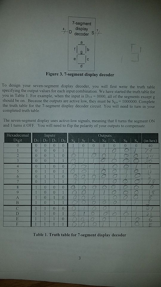
You will build a seven-segment display decoder, shown in Figure 3. The circuit has four input...
You will build a seven-segment display decoder, shown in Figure 3. The circuit has four input bits, D3:0 (representing a hexadecimal number between 0 and F), and produces seven output bits, Sa:g, that drive the seven segments to display the number. The 7-segment display we will use in this lab is a common cathode type, a segment of the display turns on when it is 1. The other type of 7-segment display is common anode, for which a segment turns...
Task 3 BCD-to-7-Segment Conversion Derive the truth table for the BCD-to-seven-segment code decoder (a truth table...
 Task 3 BCD-to-7-Segment Conversion Derive the truth table for the BCD-to-seven-segment code decoder (a truth table with 4 inputs and 7 outputs, where 6 out of 16 input combinations are invalid). Decide on how to handle outputs for illegal input com- binations and describe your choice in your discussion Task 4 Use the WinLogiLab WinBoolean utility K-Map tool to obtain a minimal all-NAND realization for the BCD-to-seven-segment decoder Task 5 Use the WinLogiLab DigitalSim utility to simulate the logic functionality...
A seven segment decoder is a digital circuit that displays an input value 0 through 9 as a digital output in the 7-segment display. The behavior of this design can be modeled with the schematic diagra...
 A seven segment decoder is a digital circuit that
displays an input value 0 through 9 as a digital output in the
7-segment display. The behavior of this design can be modeled with
the schematic diagram below, where DCBA is the 4-bit input (D is
the most significant bit and A is the least significant bit) and
abcdefg is the 7-segment output.
2. (20 POINTS) A seven segment decoder is a digital circuit that displays an input value 0 through...
A seven segment decoder is a digital circuit that
displays an input value 0 through 9 as a digital output in the
7-segment display. The behavior of this design can be modeled with
the schematic diagram below, where DCBA is the 4-bit input (D is
the most significant bit and A is the least significant bit) and
abcdefg is the 7-segment output.
2. (20 POINTS) A seven segment decoder is a digital circuit that displays an input value 0 through...
Problem 4.0 (20 Points) Design the segment 'b' of the BCD to 7 segment decoder driver of the common cathode seven segment display. Your design should include the following: Hint th e inval...
 Problem 4.0 (20 Points) Design the segment 'b' of the BCD to 7 segment decoder driver of the common cathode seven segment display. Your design should include the following: Hint th e invalid numbers can be used as don't cares Truth table K-Map Simplified Boolean expression Logic circuit implementation . .
Problem 4.0 (20 Points) Design the segment 'b' of the BCD to 7 segment decoder driver of the common cathode seven segment display. Your design should include the following:...
Problem 4.0 (20 Points) Design the segment 'b' of the BCD to 7 segment decoder driver of the common cathode seven segment display. Your design should include the following: Hint th e invalid numbers can be used as don't cares Truth table K-Map Simplified Boolean expression Logic circuit implementation . .
Problem 4.0 (20 Points) Design the segment 'b' of the BCD to 7 segment decoder driver of the common cathode seven segment display. Your design should include the following:...
please answers to all thanks. Alt Car Ripple Blanking in Seven-Segment Decoders 4. In the following...
 please answers to all thanks.
Alt Car Ripple Blanking in Seven-Segment Decoders 4. In the following drawings, four 741547 seven segment decoders are configured to suppress leading or trailing zeros, using the ripple-blanking feature of the decoder a. Complete each drawing to show how to interconnect the decaders to display the digits and blank displays as shown. [2 marks for each drawing: 4 marks totall b. Label each set of decoder inputs (DCBA, RBI) and output (RBO only) with the...
please answers to all thanks.
Alt Car Ripple Blanking in Seven-Segment Decoders 4. In the following drawings, four 741547 seven segment decoders are configured to suppress leading or trailing zeros, using the ripple-blanking feature of the decoder a. Complete each drawing to show how to interconnect the decaders to display the digits and blank displays as shown. [2 marks for each drawing: 4 marks totall b. Label each set of decoder inputs (DCBA, RBI) and output (RBO only) with the...
how to design a 7 segment truth table for an alphabet? if the output displayed 'FIRE'...
how to design a 7 segment truth table for an alphabet? if the output displayed 'FIRE' means how the truth table is it?
You need to design a BCD to 7-segment decoder, as shown in the following figure. Construct...
 You need to design a BCD to 7-segment decoder, as shown in the
following figure. Construct the truth table of the BCD-to-7 segment
decoder for the 'c1' segment. For each BCD input below, check the
box if the output for that value in the truth table is 1.
CO c5 c1 с6 c4 c2 68280 88899 со с1 с2 с3 с4 c5 сб BCD to 7-segment control signal decoder АВСD
CO c5 c1 с6 c4 c2 68280 88899 со с1...
You need to design a BCD to 7-segment decoder, as shown in the
following figure. Construct the truth table of the BCD-to-7 segment
decoder for the 'c1' segment. For each BCD input below, check the
box if the output for that value in the truth table is 1.
CO c5 c1 с6 c4 c2 68280 88899 со с1 с2 с3 с4 c5 сб BCD to 7-segment control signal decoder АВСD
CO c5 c1 с6 c4 c2 68280 88899 со с1...
**ONLY C&D PLEASE!** (100 points) You are asked to design a "HELLO" circuit in this question....
 **ONLY C&D PLEASE!**
(100 points) You are asked to design a "HELLO" circuit in this question. The inputs of the circuit are three bits x, y and z. The outputs are seven bits a, b, c, d, e, f and g controlling a 7-segment display (see Fig. 2.63(a)). For the 7-segment display, a segment is turned on when the corresponding control signal is 1. The "HELLO" circuit outputs the control signals to display the letter "H", "E", "L", "L", "O"...
**ONLY C&D PLEASE!**
(100 points) You are asked to design a "HELLO" circuit in this question. The inputs of the circuit are three bits x, y and z. The outputs are seven bits a, b, c, d, e, f and g controlling a 7-segment display (see Fig. 2.63(a)). For the 7-segment display, a segment is turned on when the corresponding control signal is 1. The "HELLO" circuit outputs the control signals to display the letter "H", "E", "L", "L", "O"...
I have a 4 input 2 output truth table and these are the simplified boolean equations...
 I have a 4 input 2 output truth table and these are the
simplified boolean equations I have. Can you design a combinational
circuit with these two equations. (Please make sure it is a 4 input
2 output diagram).
left Red + abc
I have a 4 input 2 output truth table and these are the
simplified boolean equations I have. Can you design a combinational
circuit with these two equations. (Please make sure it is a 4 input
2 output diagram).
left Red + abc
Preparation (Pre-lab) Before coming to the first lab session, complete the following tasks: Generate a truth...
 Preparation (Pre-lab) Before coming to the first lab session, complete the following tasks: Generate a truth table showing inputs vs outputs for the following circuit blocks in Part I: Comparator, Circuit A, and Circuit B. o Use the truth tables to produce minimized SOP (sum of products) for the Comparator, Circuit A and Circuit B. Part I - Simple Binary to BCD Conversion Design Specifications You are to design a circuit that converts a four-bit binary number V[3..0] = V[3]...
 Task 3 BCD-to-7-Segment Conversion Derive the truth table for the BCD-to-seven-segment code decoder (a truth table with 4 inputs and 7 outputs, where 6 out of 16 input combinations are invalid). Decide on how to handle outputs for illegal input com- binations and describe your choice in your discussion Task 4 Use the WinLogiLab WinBoolean utility K-Map tool to obtain a minimal all-NAND realization for the BCD-to-seven-segment decoder Task 5 Use the WinLogiLab DigitalSim utility to simulate the logic functionality...
 A seven segment decoder is a digital circuit that
displays an input value 0 through 9 as a digital output in the
7-segment display. The behavior of this design can be modeled with
the schematic diagram below, where DCBA is the 4-bit input (D is
the most significant bit and A is the least significant bit) and
abcdefg is the 7-segment output.
2. (20 POINTS) A seven segment decoder is a digital circuit that displays an input value 0 through...
A seven segment decoder is a digital circuit that
displays an input value 0 through 9 as a digital output in the
7-segment display. The behavior of this design can be modeled with
the schematic diagram below, where DCBA is the 4-bit input (D is
the most significant bit and A is the least significant bit) and
abcdefg is the 7-segment output.
2. (20 POINTS) A seven segment decoder is a digital circuit that displays an input value 0 through...
 Problem 4.0 (20 Points) Design the segment 'b' of the BCD to 7 segment decoder driver of the common cathode seven segment display. Your design should include the following: Hint th e invalid numbers can be used as don't cares Truth table K-Map Simplified Boolean expression Logic circuit implementation . .
Problem 4.0 (20 Points) Design the segment 'b' of the BCD to 7 segment decoder driver of the common cathode seven segment display. Your design should include the following:...
Problem 4.0 (20 Points) Design the segment 'b' of the BCD to 7 segment decoder driver of the common cathode seven segment display. Your design should include the following: Hint th e invalid numbers can be used as don't cares Truth table K-Map Simplified Boolean expression Logic circuit implementation . .
Problem 4.0 (20 Points) Design the segment 'b' of the BCD to 7 segment decoder driver of the common cathode seven segment display. Your design should include the following:...
 please answers to all thanks.
Alt Car Ripple Blanking in Seven-Segment Decoders 4. In the following drawings, four 741547 seven segment decoders are configured to suppress leading or trailing zeros, using the ripple-blanking feature of the decoder a. Complete each drawing to show how to interconnect the decaders to display the digits and blank displays as shown. [2 marks for each drawing: 4 marks totall b. Label each set of decoder inputs (DCBA, RBI) and output (RBO only) with the...
please answers to all thanks.
Alt Car Ripple Blanking in Seven-Segment Decoders 4. In the following drawings, four 741547 seven segment decoders are configured to suppress leading or trailing zeros, using the ripple-blanking feature of the decoder a. Complete each drawing to show how to interconnect the decaders to display the digits and blank displays as shown. [2 marks for each drawing: 4 marks totall b. Label each set of decoder inputs (DCBA, RBI) and output (RBO only) with the...
 You need to design a BCD to 7-segment decoder, as shown in the
following figure. Construct the truth table of the BCD-to-7 segment
decoder for the 'c1' segment. For each BCD input below, check the
box if the output for that value in the truth table is 1.
CO c5 c1 с6 c4 c2 68280 88899 со с1 с2 с3 с4 c5 сб BCD to 7-segment control signal decoder АВСD
CO c5 c1 с6 c4 c2 68280 88899 со с1...
You need to design a BCD to 7-segment decoder, as shown in the
following figure. Construct the truth table of the BCD-to-7 segment
decoder for the 'c1' segment. For each BCD input below, check the
box if the output for that value in the truth table is 1.
CO c5 c1 с6 c4 c2 68280 88899 со с1 с2 с3 с4 c5 сб BCD to 7-segment control signal decoder АВСD
CO c5 c1 с6 c4 c2 68280 88899 со с1...
 **ONLY C&D PLEASE!**
(100 points) You are asked to design a "HELLO" circuit in this question. The inputs of the circuit are three bits x, y and z. The outputs are seven bits a, b, c, d, e, f and g controlling a 7-segment display (see Fig. 2.63(a)). For the 7-segment display, a segment is turned on when the corresponding control signal is 1. The "HELLO" circuit outputs the control signals to display the letter "H", "E", "L", "L", "O"...
**ONLY C&D PLEASE!**
(100 points) You are asked to design a "HELLO" circuit in this question. The inputs of the circuit are three bits x, y and z. The outputs are seven bits a, b, c, d, e, f and g controlling a 7-segment display (see Fig. 2.63(a)). For the 7-segment display, a segment is turned on when the corresponding control signal is 1. The "HELLO" circuit outputs the control signals to display the letter "H", "E", "L", "L", "O"...
 I have a 4 input 2 output truth table and these are the
simplified boolean equations I have. Can you design a combinational
circuit with these two equations. (Please make sure it is a 4 input
2 output diagram).
left Red + abc
I have a 4 input 2 output truth table and these are the
simplified boolean equations I have. Can you design a combinational
circuit with these two equations. (Please make sure it is a 4 input
2 output diagram).
left Red + abc
 Preparation (Pre-lab) Before coming to the first lab session, complete the following tasks: Generate a truth table showing inputs vs outputs for the following circuit blocks in Part I: Comparator, Circuit A, and Circuit B. o Use the truth tables to produce minimized SOP (sum of products) for the Comparator, Circuit A and Circuit B. Part I - Simple Binary to BCD Conversion Design Specifications You are to design a circuit that converts a four-bit binary number V[3..0] = V[3]...
Most questions answered within 3 hours.
-
A study of the effects of exercise used rats bred to have high
or low capacity...
asked 11 minutes ago -
Using your data from the experiment, calculate the initial moles
of HCl that you started with....
asked 11 minutes ago -
Suppose you want to make 500 mL of a 0.20 M Tris buffer at pH
8.0....
asked 12 minutes ago -
The titanic hit an iceberg estimated to be half of her mass.
Before hitting the iceberg,...
asked 34 minutes ago -
3. The top four firms in Industry A have market shares of 30,
25, 10, and...
asked 37 minutes ago -
Are there such things as microscopic multicellular animal
parasites? If so, please give examples.
asked 1 hour ago -
1. What two structures in the ear are involved in your
sense of balance and in...
asked 58 minutes ago -
Two ice skaters suddenly push off against one another starting
from a stationary position. The 45...
asked 59 minutes ago -
What is the Larmor frequency for a proton in a magnetic field of
B0 = 14.0...
asked 1 hour ago -
Problem 03.019 Annual Worth Calculations
Find the value of x that makes the equivalent annual
worth...
asked 1 hour ago -
Under common law, right of survivorship was automatically a
feature of which type of co-tenancy?
a....
asked 1 hour ago -
At 1 bar, how much energy is required to heat 61.0 g of H2O(s)
at −12.0...
asked 1 hour ago