A seven segment decoder is a digital circuit that displays an input value 0 through 9 as a digital output in the 7-segment display. The behavior of this design can be modeled with the schematic diagram below, where DCBA is the 4-bit input (D is the most significant bit and A is the least significant bit) and abcdefg is the 7-segment output.

Homework Answers
A) Truth Table

B)
X are don't care terms.

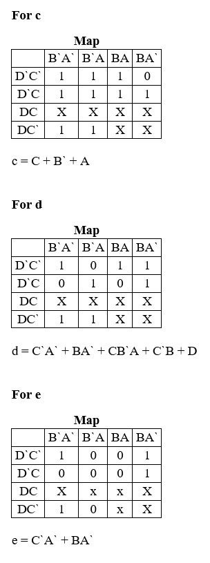

C)


Kindly give a thumbs up, if found useful. Comment for queries. :)
Add Answer to:
A seven segment decoder is a digital circuit that displays an input value 0 through 9 as a digital output in the 7-segment display. The behavior of this design can be modeled with the schematic diagra...
You will build a seven-segment display decoder, shown in Figure 3. The circuit has four input...
You will build a seven-segment display decoder, shown in Figure 3. The circuit has four input bits, D3:0 (representing a hexadecimal number between 0 and F), and produces seven output bits, Sa:g, that drive the seven segments to display the number. The 7-segment display we will use in this lab is a common cathode type, a segment of the display turns on when it is 1. The other type of 7-segment display is common anode, for which a segment turns...
Problem 4.0 (20 Points) Design the segment 'b' of the BCD to 7 segment decoder driver of the common cathode seven segment display. Your design should include the following: Hint th e inval...
 Problem 4.0 (20 Points) Design the segment 'b' of the BCD to 7 segment decoder driver of the common cathode seven segment display. Your design should include the following: Hint th e invalid numbers can be used as don't cares Truth table K-Map Simplified Boolean expression Logic circuit implementation . .
Problem 4.0 (20 Points) Design the segment 'b' of the BCD to 7 segment decoder driver of the common cathode seven segment display. Your design should include the following:...
Problem 4.0 (20 Points) Design the segment 'b' of the BCD to 7 segment decoder driver of the common cathode seven segment display. Your design should include the following: Hint th e invalid numbers can be used as don't cares Truth table K-Map Simplified Boolean expression Logic circuit implementation . .
Problem 4.0 (20 Points) Design the segment 'b' of the BCD to 7 segment decoder driver of the common cathode seven segment display. Your design should include the following:...
please answers to all thanks. Alt Car Ripple Blanking in Seven-Segment Decoders 4. In the following...
 please answers to all thanks.
Alt Car Ripple Blanking in Seven-Segment Decoders 4. In the following drawings, four 741547 seven segment decoders are configured to suppress leading or trailing zeros, using the ripple-blanking feature of the decoder a. Complete each drawing to show how to interconnect the decaders to display the digits and blank displays as shown. [2 marks for each drawing: 4 marks totall b. Label each set of decoder inputs (DCBA, RBI) and output (RBO only) with the...
please answers to all thanks.
Alt Car Ripple Blanking in Seven-Segment Decoders 4. In the following drawings, four 741547 seven segment decoders are configured to suppress leading or trailing zeros, using the ripple-blanking feature of the decoder a. Complete each drawing to show how to interconnect the decaders to display the digits and blank displays as shown. [2 marks for each drawing: 4 marks totall b. Label each set of decoder inputs (DCBA, RBI) and output (RBO only) with the...
after completing the truth table, write equations for each output segment. ( through Sa-Sg so 7...
 after completing the truth table, write equations for each output
segment. ( through Sa-Sg so 7 equations) using k-maps
next translate your equations into logic gates using
only ONE design for all the equations.
7-segment 4, display7 decoder S Figure 3.7-segment display decoder To design your seven-segment display decoder, you will first write the truth table specifying the output values for each input combination. We have started the truth table for you in Table 1. For example, when the input...
after completing the truth table, write equations for each output
segment. ( through Sa-Sg so 7 equations) using k-maps
next translate your equations into logic gates using
only ONE design for all the equations.
7-segment 4, display7 decoder S Figure 3.7-segment display decoder To design your seven-segment display decoder, you will first write the truth table specifying the output values for each input combination. We have started the truth table for you in Table 1. For example, when the input...
Task 1: One implementation of a multiplexer uses a decoder. Using Logic Circuit,create a new schematic,...
 Task 1: One implementation of a multiplexer uses a decoder. Using Logic Circuit,create a new schematic, import one of the decoders created in a previous lab and create a logic dircuit that implements the truth table below Task 2: Create a logic circuit that can display two 4-bit digits on two 7-segment displays using a single 7- segment display decoder and 4 multiplexers. To do this you will use four switches to enter the first number, and a second set...
4. Design a combinational circuit for a BCD to seven-segment code converter that will input a...
 4. Design a combinational circuit for a BCD to seven-segment code converter that will input a BCD number and output t on a seven segment common- anode display. The code converter will only display the number 8. Thoe converter wil turn the display OFF for all other valid BCD digits except digit 9 which will never occur. Draw a schematic. Show all steps clearly.
Design the logic circuit to display a 3 bit octal numbers from 0 to 7 on...
 Design the logic circuit to display a 3 bit octal numbers from 0 to 7 on a seven segment display shown below (for number 1 use segments b and c; for 6 include segment (a) Write the Truth Table with A, B. C representing the input bits (A is the MSB) and a, b, c, d, e, f and g representing the outputs to the seven segments. (b) Implement the circuit using a Programmable Logic Array (use simplified notation to...
show its derivation to get the full mark. 2. (10 marks) 0 3 Figure 2: Mapping...
 show its derivation to get the full mark. 2. (10 marks) 0 3 Figure 2: Mapping from input bits to different LED segments on a SSD Design a structural System Verilog module for a 7 segment display decoder that has a four bit input C, and produces a seven bit outpt Y which can be used to display the character associated with the hexadecimal value of C on a 7-segment display. The seven segments in the display are identified with...
The seven-segment indicator (shown in the figure) can be used to display any of the decimal digits 0 through 9. For example "1" is displayed by lighting segment 2 and 3 and "8" by...
 The seven-segment indicator (shown in the figure) can be used to display any of the decimal digits 0 through 9. For example "1" is displayed by lighting segment 2 and 3 and "8" by lighting all seven segments. A segment is lighted when logic 1 is applied to the corresponding input on the display module. Circuit to be aputs From Switche l p Designed Design an excess-3 code convertor to derive a seven segment indicator. The four inputs to the...
Create the logic diagram for this circuit Create a binary to hexadecimal converter. Use SW3-0 as the input and the left most 7 segment display ONLY as the output. SW3-0 should be interpreted as a 4bi...
 Create the logic diagram for this circuit
Create a binary to hexadecimal converter. Use SW3-0 as the input and the left most 7 segment display ONLY as the output. SW3-0 should be interpreted as a 4bit unsigned binary number with SW3 as the MSB. The 7 segment should display 0-F based on the input number, both upper and lower case may be used. You need to show to the marker:
Create a binary to hexadecimal converter. Use SW3-0 as the...
Create the logic diagram for this circuit
Create a binary to hexadecimal converter. Use SW3-0 as the input and the left most 7 segment display ONLY as the output. SW3-0 should be interpreted as a 4bit unsigned binary number with SW3 as the MSB. The 7 segment should display 0-F based on the input number, both upper and lower case may be used. You need to show to the marker:
Create a binary to hexadecimal converter. Use SW3-0 as the...
 Problem 4.0 (20 Points) Design the segment 'b' of the BCD to 7 segment decoder driver of the common cathode seven segment display. Your design should include the following: Hint th e invalid numbers can be used as don't cares Truth table K-Map Simplified Boolean expression Logic circuit implementation . .
Problem 4.0 (20 Points) Design the segment 'b' of the BCD to 7 segment decoder driver of the common cathode seven segment display. Your design should include the following:...
Problem 4.0 (20 Points) Design the segment 'b' of the BCD to 7 segment decoder driver of the common cathode seven segment display. Your design should include the following: Hint th e invalid numbers can be used as don't cares Truth table K-Map Simplified Boolean expression Logic circuit implementation . .
Problem 4.0 (20 Points) Design the segment 'b' of the BCD to 7 segment decoder driver of the common cathode seven segment display. Your design should include the following:...
 please answers to all thanks.
Alt Car Ripple Blanking in Seven-Segment Decoders 4. In the following drawings, four 741547 seven segment decoders are configured to suppress leading or trailing zeros, using the ripple-blanking feature of the decoder a. Complete each drawing to show how to interconnect the decaders to display the digits and blank displays as shown. [2 marks for each drawing: 4 marks totall b. Label each set of decoder inputs (DCBA, RBI) and output (RBO only) with the...
please answers to all thanks.
Alt Car Ripple Blanking in Seven-Segment Decoders 4. In the following drawings, four 741547 seven segment decoders are configured to suppress leading or trailing zeros, using the ripple-blanking feature of the decoder a. Complete each drawing to show how to interconnect the decaders to display the digits and blank displays as shown. [2 marks for each drawing: 4 marks totall b. Label each set of decoder inputs (DCBA, RBI) and output (RBO only) with the...
 after completing the truth table, write equations for each output
segment. ( through Sa-Sg so 7 equations) using k-maps
next translate your equations into logic gates using
only ONE design for all the equations.
7-segment 4, display7 decoder S Figure 3.7-segment display decoder To design your seven-segment display decoder, you will first write the truth table specifying the output values for each input combination. We have started the truth table for you in Table 1. For example, when the input...
after completing the truth table, write equations for each output
segment. ( through Sa-Sg so 7 equations) using k-maps
next translate your equations into logic gates using
only ONE design for all the equations.
7-segment 4, display7 decoder S Figure 3.7-segment display decoder To design your seven-segment display decoder, you will first write the truth table specifying the output values for each input combination. We have started the truth table for you in Table 1. For example, when the input...
 Task 1: One implementation of a multiplexer uses a decoder. Using Logic Circuit,create a new schematic, import one of the decoders created in a previous lab and create a logic dircuit that implements the truth table below Task 2: Create a logic circuit that can display two 4-bit digits on two 7-segment displays using a single 7- segment display decoder and 4 multiplexers. To do this you will use four switches to enter the first number, and a second set...
 4. Design a combinational circuit for a BCD to seven-segment code converter that will input a BCD number and output t on a seven segment common- anode display. The code converter will only display the number 8. Thoe converter wil turn the display OFF for all other valid BCD digits except digit 9 which will never occur. Draw a schematic. Show all steps clearly.
 Design the logic circuit to display a 3 bit octal numbers from 0 to 7 on a seven segment display shown below (for number 1 use segments b and c; for 6 include segment (a) Write the Truth Table with A, B. C representing the input bits (A is the MSB) and a, b, c, d, e, f and g representing the outputs to the seven segments. (b) Implement the circuit using a Programmable Logic Array (use simplified notation to...
 show its derivation to get the full mark. 2. (10 marks) 0 3 Figure 2: Mapping from input bits to different LED segments on a SSD Design a structural System Verilog module for a 7 segment display decoder that has a four bit input C, and produces a seven bit outpt Y which can be used to display the character associated with the hexadecimal value of C on a 7-segment display. The seven segments in the display are identified with...
 The seven-segment indicator (shown in the figure) can be used to display any of the decimal digits 0 through 9. For example "1" is displayed by lighting segment 2 and 3 and "8" by lighting all seven segments. A segment is lighted when logic 1 is applied to the corresponding input on the display module. Circuit to be aputs From Switche l p Designed Design an excess-3 code convertor to derive a seven segment indicator. The four inputs to the...
 Create the logic diagram for this circuit
Create a binary to hexadecimal converter. Use SW3-0 as the input and the left most 7 segment display ONLY as the output. SW3-0 should be interpreted as a 4bit unsigned binary number with SW3 as the MSB. The 7 segment should display 0-F based on the input number, both upper and lower case may be used. You need to show to the marker:
Create a binary to hexadecimal converter. Use SW3-0 as the...
Create the logic diagram for this circuit
Create a binary to hexadecimal converter. Use SW3-0 as the input and the left most 7 segment display ONLY as the output. SW3-0 should be interpreted as a 4bit unsigned binary number with SW3 as the MSB. The 7 segment should display 0-F based on the input number, both upper and lower case may be used. You need to show to the marker:
Create a binary to hexadecimal converter. Use SW3-0 as the...
Most questions answered within 3 hours.
-
The American Heart Association is about to conduct an
anti-smoking campaign and wants to know the...
asked 5 minutes ago -
An isolated charged conducting sphere has a radius R =
15.0 cm. At a distance of...
asked 4 minutes ago -
Building an ERD: In your own words please explain the first step
in building an entity-relationship...
asked 6 minutes ago -
Daniella is considering the purchase of a 10-year, $10,000 bond
being issued by Disreputable, Inc. The...
asked 13 minutes ago -
This is a homework for MATLAB. Please answer using MATLAB
functions and parameters. The answers are...
asked 13 minutes ago -
1. Which of the following is a cost of unemployment? a.
Unemployed individuals suffer a loss...
asked 25 minutes ago -
What z Score do we need in order to have a total of 1% (or less)...
asked 32 minutes ago -
Which of the following is a query that you CANNOT write in
Standard SQL over a...
asked 42 minutes ago -
If all I have is a mean concentration, how can I
calculate the overall confidence limit,...
asked 36 minutes ago -
In the lab, you prepare a solution in a 150 mL volumetric flask
by mixing 25.0...
asked 43 minutes ago -
1. Consider the reaction: 2 NO (g) + 2 H2 (g) → N2 (g) + 2...
asked 44 minutes ago -
The equilibrium constant for the dissociation of trichloroacetic
acid at STP is 1.995 x 10^-1. What...
asked 51 minutes ago