
Homework Answers
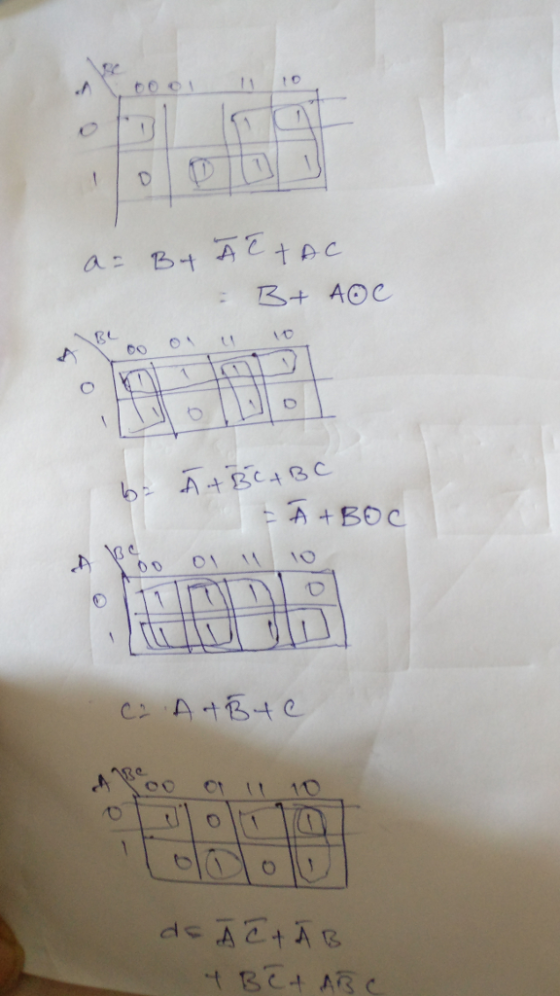
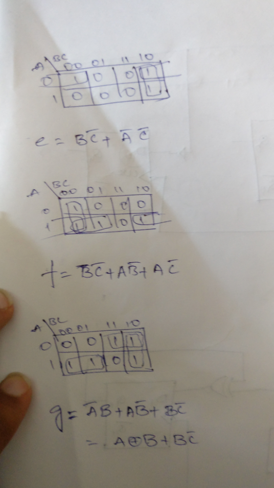
TRUTH TABLE:
| A | B | C | a | b | c | d | e | f | g |
|---|---|---|---|---|---|---|---|---|---|
| 0 | 0 | 0 | 1 | 1 | 1 | 1 | 1 | 1 | 0 |
| 0 | 0 | 1 | 0 | 1 | 1 | 0 | 0 | 0 | 0 |
| 0 | 1 | 0 | 1 | 1 | 0 | 1 | 1 | 0 | 1 |
| 0 | 1 | 1 | 1 | 1 | 1 | 1 | 0 | 0 | 1 |
| 1 | 0 | 0 | 0 | 1 | 1 | 0 | 0 | 1 | 1 |
| 1 | 0 | 1 | 1 | 0 | 1 | 1 | 0 | 1 | 1 |
| 1 | 1 | 0 | 1 | 0 | 1 | 1 | 1 | 1 | 1 |
| 1 | 1 | 1 | 1 | 1 | 1 | 0 | 0 | 0 | 0 |
Logic Equations:
CIRCUIT:

Add Answer to:
Design the logic circuit to display a 3 bit octal numbers from 0 to 7 on...
You will build a seven-segment display decoder, shown in Figure 3. The circuit has four input...
You will build a seven-segment display decoder, shown in Figure 3. The circuit has four input bits, D3:0 (representing a hexadecimal number between 0 and F), and produces seven output bits, Sa:g, that drive the seven segments to display the number. The 7-segment display we will use in this lab is a common cathode type, a segment of the display turns on when it is 1. The other type of 7-segment display is common anode, for which a segment turns...
Design a circuit to add two 2-bit binary numbers and display the results of the addition...
Design a circuit to add two 2-bit binary numbers and display the results of the addition as a 3-bit binary number, with the most significant bit be the carry out. To do this, you will use the four switches on your Breadboard Companion as your two 2-bit number inputs. Three of your LEDs will be used to represent the 3-bit output of your circuit. Complete a truth table for the expected output values on the lab data sheet attached. Use...
**ONLY C&D PLEASE!** (100 points) You are asked to design a "HELLO" circuit in this question....
 **ONLY C&D PLEASE!**
(100 points) You are asked to design a "HELLO" circuit in this question. The inputs of the circuit are three bits x, y and z. The outputs are seven bits a, b, c, d, e, f and g controlling a 7-segment display (see Fig. 2.63(a)). For the 7-segment display, a segment is turned on when the corresponding control signal is 1. The "HELLO" circuit outputs the control signals to display the letter "H", "E", "L", "L", "O"...
**ONLY C&D PLEASE!**
(100 points) You are asked to design a "HELLO" circuit in this question. The inputs of the circuit are three bits x, y and z. The outputs are seven bits a, b, c, d, e, f and g controlling a 7-segment display (see Fig. 2.63(a)). For the 7-segment display, a segment is turned on when the corresponding control signal is 1. The "HELLO" circuit outputs the control signals to display the letter "H", "E", "L", "L", "O"...
The seven-segment indicator (shown in the figure) can be used to display any of the decimal digits 0 through 9. For example "1" is displayed by lighting segment 2 and 3 and "8" by...
 The seven-segment indicator (shown in the figure) can be used to display any of the decimal digits 0 through 9. For example "1" is displayed by lighting segment 2 and 3 and "8" by lighting all seven segments. A segment is lighted when logic 1 is applied to the corresponding input on the display module. Circuit to be aputs From Switche l p Designed Design an excess-3 code convertor to derive a seven segment indicator. The four inputs to the...
You are to design a circuit that calculates the Hamming distance between two 5-bit numbers. It...
You are to design a circuit that calculates the Hamming distance between two 5-bit numbers. It takes two 5-bit binary numbers A4 A3 A2 A1 A0 and B4 B3B 2B1 B0 as inputs and returns the number of bits that are different between the two numbers as the 3-bit binary output O2 O1 O0. For example: *If the two input numbers were 10111 and 00001 then the output would be 011 as there are 3 bits different between them. *If...
FIRST ACTIVITY: (100/100) . SIMPLE 4-BIT ARITHMETIC LOGIC UNIT (ALU): This circuit selects between arithmetic (absolute...
 FIRST ACTIVITY: (100/100) . SIMPLE 4-BIT ARITHMETIC LOGIC UNIT (ALU): This circuit selects between arithmetic (absolute value, addition) and logical (XOR, AND) operations. Only one result (hexadecimal value) can be shown on the 7-segment display This is selected by the input sel (1..0) B A-BI A+B A xnor B A nand B Input EN: If EN-1result appears on the 7 segment display. If EN=0 → all LEDs in the 7 segment display are off Arithmetic operations: The 4-bit inputs A...
A combinational circuit is used to control a seven-segment display of decimal digits, as shown in...
 A combinational circuit is used to control a seven-segment display of decimal digits, as shown in Figure 11.35. The circuit has four inputs, which provide the four-bit code used in packed decimal representation (0_10=0000, ..., 9_10=1001). The seven outputs define which segments will be activated to display a given decimal digit. Note that some combinations of inputs and outputs are not needed. Develop a truth table for this circuit. Express the truth table in SOP form. Express the truth table...
A seven segment decoder is a digital circuit that displays an input value 0 through 9 as a digital output in the 7-segment display. The behavior of this design can be modeled with the schematic diagra...
 A seven segment decoder is a digital circuit that
displays an input value 0 through 9 as a digital output in the
7-segment display. The behavior of this design can be modeled with
the schematic diagram below, where DCBA is the 4-bit input (D is
the most significant bit and A is the least significant bit) and
abcdefg is the 7-segment output.
2. (20 POINTS) A seven segment decoder is a digital circuit that displays an input value 0 through...
A seven segment decoder is a digital circuit that
displays an input value 0 through 9 as a digital output in the
7-segment display. The behavior of this design can be modeled with
the schematic diagram below, where DCBA is the 4-bit input (D is
the most significant bit and A is the least significant bit) and
abcdefg is the 7-segment output.
2. (20 POINTS) A seven segment decoder is a digital circuit that displays an input value 0 through...
In this problem, you will design a 4-bit 2's complement sub tractor, implement it in Logic...
 In this problem, you will design a 4-bit 2's complement sub tractor, implement it in Logic works, and test it. The 4-bit sub tractor works as follows: given two numbers X and Y in 2's complement binary representation on 4 bits, it outputs a 4-bit value representing X - Y in 2's complement. To obtain full marks, the following requirements must be met: You are only allowed to use basic gates, including NOT, AND, OR, NAND, NOR, XOR, XNOR. (You...
Acer Question Three Design a circuit with t wo inputs x & y representing the bits in a binary num...
 acer Question Three Design a circuit with t wo inputs x & y representing the bits in a binary number and outputs a& b also representing bits in a binary number. When t output is reversed. When the input is 1 and 3, the output s O and 2, the Any carry forward is discarded a) Show your truth table b) Find and simplify the Boolean expression for the o utputs a & b. c) Draw one logic circuit to...
 **ONLY C&D PLEASE!**
(100 points) You are asked to design a "HELLO" circuit in this question. The inputs of the circuit are three bits x, y and z. The outputs are seven bits a, b, c, d, e, f and g controlling a 7-segment display (see Fig. 2.63(a)). For the 7-segment display, a segment is turned on when the corresponding control signal is 1. The "HELLO" circuit outputs the control signals to display the letter "H", "E", "L", "L", "O"...
**ONLY C&D PLEASE!**
(100 points) You are asked to design a "HELLO" circuit in this question. The inputs of the circuit are three bits x, y and z. The outputs are seven bits a, b, c, d, e, f and g controlling a 7-segment display (see Fig. 2.63(a)). For the 7-segment display, a segment is turned on when the corresponding control signal is 1. The "HELLO" circuit outputs the control signals to display the letter "H", "E", "L", "L", "O"...
 The seven-segment indicator (shown in the figure) can be used to display any of the decimal digits 0 through 9. For example "1" is displayed by lighting segment 2 and 3 and "8" by lighting all seven segments. A segment is lighted when logic 1 is applied to the corresponding input on the display module. Circuit to be aputs From Switche l p Designed Design an excess-3 code convertor to derive a seven segment indicator. The four inputs to the...
 FIRST ACTIVITY: (100/100) . SIMPLE 4-BIT ARITHMETIC LOGIC UNIT (ALU): This circuit selects between arithmetic (absolute value, addition) and logical (XOR, AND) operations. Only one result (hexadecimal value) can be shown on the 7-segment display This is selected by the input sel (1..0) B A-BI A+B A xnor B A nand B Input EN: If EN-1result appears on the 7 segment display. If EN=0 → all LEDs in the 7 segment display are off Arithmetic operations: The 4-bit inputs A...
 A combinational circuit is used to control a seven-segment display of decimal digits, as shown in Figure 11.35. The circuit has four inputs, which provide the four-bit code used in packed decimal representation (0_10=0000, ..., 9_10=1001). The seven outputs define which segments will be activated to display a given decimal digit. Note that some combinations of inputs and outputs are not needed. Develop a truth table for this circuit. Express the truth table in SOP form. Express the truth table...
 A seven segment decoder is a digital circuit that
displays an input value 0 through 9 as a digital output in the
7-segment display. The behavior of this design can be modeled with
the schematic diagram below, where DCBA is the 4-bit input (D is
the most significant bit and A is the least significant bit) and
abcdefg is the 7-segment output.
2. (20 POINTS) A seven segment decoder is a digital circuit that displays an input value 0 through...
A seven segment decoder is a digital circuit that
displays an input value 0 through 9 as a digital output in the
7-segment display. The behavior of this design can be modeled with
the schematic diagram below, where DCBA is the 4-bit input (D is
the most significant bit and A is the least significant bit) and
abcdefg is the 7-segment output.
2. (20 POINTS) A seven segment decoder is a digital circuit that displays an input value 0 through...
 In this problem, you will design a 4-bit 2's complement sub tractor, implement it in Logic works, and test it. The 4-bit sub tractor works as follows: given two numbers X and Y in 2's complement binary representation on 4 bits, it outputs a 4-bit value representing X - Y in 2's complement. To obtain full marks, the following requirements must be met: You are only allowed to use basic gates, including NOT, AND, OR, NAND, NOR, XOR, XNOR. (You...
 acer Question Three Design a circuit with t wo inputs x & y representing the bits in a binary number and outputs a& b also representing bits in a binary number. When t output is reversed. When the input is 1 and 3, the output s O and 2, the Any carry forward is discarded a) Show your truth table b) Find and simplify the Boolean expression for the o utputs a & b. c) Draw one logic circuit to...
Most questions answered within 3 hours.
-
In a survey of 1147 small-business owners, the following
question was posed: Would you recommend working...
asked 16 minutes ago -
The value of the equilibrium constant Kc for the reaction
N2(g)+3H2(g)⇌2NH3(g) changes in the following manner...
asked 23 minutes ago -
There are two flasks on the bench top, one flask contains a 0.50
M NaCl solution...
asked 29 minutes ago -
Which of the following aqueous solutions are good buffer
systems?
.
0.10 M hydrofluoric acid +...
asked 30 minutes ago -
2. An S election is terminated if the S corporation has passive
investment income in excess...
asked 32 minutes ago -
Part of an ANOVA table is shown below.
Source of
Variation
Sum of
Squares
Degrees of...
asked 49 minutes ago -
Business process improvement initiatives often include
introducing new technology to support the new or changed ways...
asked 55 minutes ago -
Review your choice of either Agile or the Waterfall models and
for each of the 22...
asked 56 minutes ago -
Suppose an x distribution has mean μ = 4.
Consider two corresponding
x
distributions, the first...
asked 58 minutes ago -
A study of the effects of exercise used rats bred to have high
or low capacity...
asked 1 hour ago -
Using your data from the experiment, calculate the initial moles
of HCl that you started with....
asked 1 hour ago -
Suppose you want to make 500 mL of a 0.20 M Tris buffer at pH
8.0....
asked 1 hour ago