
Homework Answers
U yanarina uyun Question 1 10 pts In the figure, take R, -3.00 KO, R2 -...
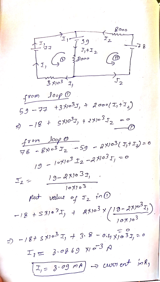
 U yanarina uyun Question 1 10 pts In the figure, take R, -3.00 KO, R2 - 2.00 KO, R; -5.00 K0 and - 77.0.2 - 56.0 V. =77.0V. Using Kirchhoff's rules, find the current in resistor R, in Figure. (Your result must be in mA's. Include 2 digit after the decimal point and maximum of 5% of error is accepted in your answer.) Next Not surved Submit Qul
Table 3 (5 points) AV1_5.0 V R(22) im(A) (A) % Error R1 100 R2 200 0.005...
 Table 3 (5 points) AV1_5.0 V R(22) im(A) (A) % Error R1 100 R2 200 0.005 R3 ! 3300 0.006 R400 .OZU R5 w 200 0.005 3. Using Kirchhoff's Rules, construct enough mathematically independent equations to solve for the current of each resistor. Then calculate the % error between your measured and theoretical values for the current of each resistor. You MUST use Kirchhoff's Rules and show work to receive any credit. (15 points) 3R5 NAV Rz
Find the potential difference across each resistor in the figure below. (R = 4.70 A, R2...
 Find the potential difference across each resistor in the figure below. (R = 4.70 A, R2 = 4.20 , R3 = 2.80 N, RA = 1.60 ) 12.0 V 3.00 V 18.0 V I RIŞ RŞR lu R AV, X Apply Kirchhoff's rules to write a set of simultaneous equations that can be solved for the current through the resistor R, AV, - AV- AVA V V V
Consider the circuit shown in the figure. Take R1 = 2R, R2=R and R3=R
 Consider the circuit shown in the figure. Take R1 = 2R, R2=R and R3=R. Find the magnitude of the current passing through the resistor R1 in terms of V/R.
Please answer clearly Question 2 The amplifier shown in Figure 2 has the following parameters: Kn(W/L)-1 mA/V2, V-1 V Determine a) Voltage gain (Vo/vi) b) Input resistance (R) c) Output resistance (R...
 Please answer clearly
Question 2 The amplifier shown in Figure 2 has the following parameters: Kn(W/L)-1 mA/V2, V-1 V Determine a) Voltage gain (Vo/vi) b) Input resistance (R) c) Output resistance (Ro) d) Maximum output voltage swing so as the amplifier stays in saturation mode. Assume VDD-20 V, R1-2.5 ΚΩ, R2-1KQ, R3-0.5 ΚΩ, R4-5 MQ, R5_1ΜΩ. R4 R1 R5 R2 Ro R3
Question 2 The amplifier shown in Figure 2 has the following parameters: Kn(W/L)-1 mA/V2, V-1 V Determine a)...
Please answer clearly
Question 2 The amplifier shown in Figure 2 has the following parameters: Kn(W/L)-1 mA/V2, V-1 V Determine a) Voltage gain (Vo/vi) b) Input resistance (R) c) Output resistance (Ro) d) Maximum output voltage swing so as the amplifier stays in saturation mode. Assume VDD-20 V, R1-2.5 ΚΩ, R2-1KQ, R3-0.5 ΚΩ, R4-5 MQ, R5_1ΜΩ. R4 R1 R5 R2 Ro R3
Question 2 The amplifier shown in Figure 2 has the following parameters: Kn(W/L)-1 mA/V2, V-1 V Determine a)...
The circuit shown in the figure below contains three resistors (R1, R2, and R) and three...
 The circuit shown in the figure below contains three resistors (R1, R2, and R) and three batteries (VA, V8, and Vc). The resistor values are: R1=2 Ohms, R2=R3=4 Ohms, and the battery voltages are VA=25 V, V8=15 V, and Vc=20 V. When the circuit is connected, what will be the power dissipated by R3? Vc R1 VA +1 R2 R3 C 1.25 W 2.0 W 5.0 W C 6.25 W 8.13 W
Consider the circuit shown in the figure(Figure 1). Suppose the four resistors in this circuit have...
 Consider the circuit shown in the figure(Figure 1). Suppose the four resistors in this circuit have the values R1 = 12 12, R2 = 7.0 N, R3 = 7.9 2 , and R4 = 12 12, and that the emf of the battery is € = 18 V You may want to review (Pages 748 - 751) Part A Find the current through each resistor using the rules for series and parallel resistors. Express vour answers using two significant figures...
In the circuit shown in the figure. R1 = 15,00 Ohm, R2 = 10.0 Ohm, R3...
 In the circuit shown in the figure. R1 = 15,00 Ohm, R2 = 10.0 Ohm, R3 = 5.0 Ohm, V emf,1 = 15.0 V. and Vemf,2 = 10.0 V. Using Kirchhoff's Loop and Junction Rules, determine the currents i1, i2, and i3 flowing through R1, R2, and R3, respectively, in the direction indicated in the figure.
6. Six resistors R1=5.00 92, R2=8.00 92, R3=14.0 2, R4=10.0 22, R5=10.0 12, and R6=3.00 22...
 6. Six resistors R1=5.00 92, R2=8.00 92, R3=14.0 2, R4=10.0 22, R5=10.0 12, and R6=3.00 22 are mounted as shown in the figure. The voltage of the battery is V= 18 Volts. What is the power dissipated in the R3 resistor? Watts 'Ro WWW R3 R,
Question 8 5 pts The circuit shown in the figure below contains three resistors (R1, R2,...
 Question 8 5 pts The circuit shown in the figure below contains three resistors (R1, R2, and R3) and three batteries (VA, VB, and Vc). The resistor values are: R1=2 Ohms, R2=R3=4 Ohms, and the battery voltages are VA=25 V, VB=15 V, and Vc=20 V. When the circuit is connected, what will be the power dissipated by R1? VC + R1 + VA VB R2 M R3 1.25 W 2.0 W 12.5 W 6.25 W 8.13 W
 U yanarina uyun Question 1 10 pts In the figure, take R, -3.00 KO, R2 - 2.00 KO, R; -5.00 K0 and - 77.0.2 - 56.0 V. =77.0V. Using Kirchhoff's rules, find the current in resistor R, in Figure. (Your result must be in mA's. Include 2 digit after the decimal point and maximum of 5% of error is accepted in your answer.) Next Not surved Submit Qul
 Table 3 (5 points) AV1_5.0 V R(22) im(A) (A) % Error R1 100 R2 200 0.005 R3 ! 3300 0.006 R400 .OZU R5 w 200 0.005 3. Using Kirchhoff's Rules, construct enough mathematically independent equations to solve for the current of each resistor. Then calculate the % error between your measured and theoretical values for the current of each resistor. You MUST use Kirchhoff's Rules and show work to receive any credit. (15 points) 3R5 NAV Rz
 Find the potential difference across each resistor in the figure below. (R = 4.70 A, R2 = 4.20 , R3 = 2.80 N, RA = 1.60 ) 12.0 V 3.00 V 18.0 V I RIŞ RŞR lu R AV, X Apply Kirchhoff's rules to write a set of simultaneous equations that can be solved for the current through the resistor R, AV, - AV- AVA V V V
 Please answer clearly
Question 2 The amplifier shown in Figure 2 has the following parameters: Kn(W/L)-1 mA/V2, V-1 V Determine a) Voltage gain (Vo/vi) b) Input resistance (R) c) Output resistance (Ro) d) Maximum output voltage swing so as the amplifier stays in saturation mode. Assume VDD-20 V, R1-2.5 ΚΩ, R2-1KQ, R3-0.5 ΚΩ, R4-5 MQ, R5_1ΜΩ. R4 R1 R5 R2 Ro R3
Question 2 The amplifier shown in Figure 2 has the following parameters: Kn(W/L)-1 mA/V2, V-1 V Determine a)...
Please answer clearly
Question 2 The amplifier shown in Figure 2 has the following parameters: Kn(W/L)-1 mA/V2, V-1 V Determine a) Voltage gain (Vo/vi) b) Input resistance (R) c) Output resistance (Ro) d) Maximum output voltage swing so as the amplifier stays in saturation mode. Assume VDD-20 V, R1-2.5 ΚΩ, R2-1KQ, R3-0.5 ΚΩ, R4-5 MQ, R5_1ΜΩ. R4 R1 R5 R2 Ro R3
Question 2 The amplifier shown in Figure 2 has the following parameters: Kn(W/L)-1 mA/V2, V-1 V Determine a)...
 The circuit shown in the figure below contains three resistors (R1, R2, and R) and three batteries (VA, V8, and Vc). The resistor values are: R1=2 Ohms, R2=R3=4 Ohms, and the battery voltages are VA=25 V, V8=15 V, and Vc=20 V. When the circuit is connected, what will be the power dissipated by R3? Vc R1 VA +1 R2 R3 C 1.25 W 2.0 W 5.0 W C 6.25 W 8.13 W
 Consider the circuit shown in the figure(Figure 1). Suppose the four resistors in this circuit have the values R1 = 12 12, R2 = 7.0 N, R3 = 7.9 2 , and R4 = 12 12, and that the emf of the battery is € = 18 V You may want to review (Pages 748 - 751) Part A Find the current through each resistor using the rules for series and parallel resistors. Express vour answers using two significant figures...
 In the circuit shown in the figure. R1 = 15,00 Ohm, R2 = 10.0 Ohm, R3 = 5.0 Ohm, V emf,1 = 15.0 V. and Vemf,2 = 10.0 V. Using Kirchhoff's Loop and Junction Rules, determine the currents i1, i2, and i3 flowing through R1, R2, and R3, respectively, in the direction indicated in the figure.
 6. Six resistors R1=5.00 92, R2=8.00 92, R3=14.0 2, R4=10.0 22, R5=10.0 12, and R6=3.00 22 are mounted as shown in the figure. The voltage of the battery is V= 18 Volts. What is the power dissipated in the R3 resistor? Watts 'Ro WWW R3 R,
 Question 8 5 pts The circuit shown in the figure below contains three resistors (R1, R2, and R3) and three batteries (VA, VB, and Vc). The resistor values are: R1=2 Ohms, R2=R3=4 Ohms, and the battery voltages are VA=25 V, VB=15 V, and Vc=20 V. When the circuit is connected, what will be the power dissipated by R1? VC + R1 + VA VB R2 M R3 1.25 W 2.0 W 12.5 W 6.25 W 8.13 W
Most questions answered within 3 hours.
-
How can I solve the following using a TI83
Claim: Most adults would erase all of...
asked 10 minutes ago -
Analysis of 3-ethyl-3-buten-2-ol gave C, 72.13%; H, 11.92%.
Calculate the percent deviation of these results from...
asked 7 minutes ago -
Which VALS segment is most likely to have a top of the line
brand new (2015)...
asked 11 minutes ago -
Write a program to score the paper-rock-scissor game. Each of
two users types in either P,R...
asked 31 minutes ago -
Calculate the equillibrium constent K for a redox reaction that
has E°cell = -.98 V at...
asked 43 minutes ago -
A concave spherical mirror has a radius of curvature of
magnitude 19.6 cm.
(a) Find the...
asked 45 minutes ago -
3. draw a diagram of the magnetic field:
a. around a long straight wire with a...
asked 44 minutes ago -
If you titrated 30.0 mL of 0.1 M HCl with 0.1 M NaOH, indicate
the approximate...
asked 52 minutes ago -
NADH passes electrons into the electron transport chain. List
the carriers that would receive the electrons,...
asked 1 hour ago -
A cylindrical cable with a resistivity of 1.6x10⁻⁸ Ω·m and cross
sectional area of 3x10⁻⁵ m^2...
asked 1 hour ago -
True or False.
A consumer with convex preferences who is indifferent between
the bundles (5,2) and...
asked 1 hour ago -
A diamond's index of refraction for red light, 656 nm, is 2.410,
while that for blue...
asked 1 hour ago