Method 1: Mathematical Approach
Method 2: Engineering Approach

Homework Answers


Add Answer to:
Method 1: Mathematical Approach
Method 2: Engineering Approach
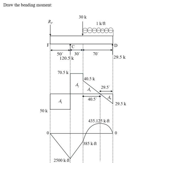
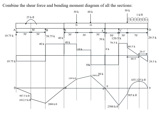
Draw the shear and bending moment diagram for...
2. Draw Shear Force and Bending Moment Diagram (use your preferred method). Determine Maximum Ten...
 2. Draw Shear Force and Bending Moment Diagram (use your preferred method). Determine Maximum Tensile and Compressive Stresses due to bending, state where on the beam these occur. For the mid-point between A and B, determine shear stress at neutral axis; 2" from the top of the flange; at the junction between web and flange and on the top of the flange for the cross-section. Plot of the bending stress and shear stress distribution diagram across the cross section of...
QUESTION 4 4. Bending Moment in a Beam Draw the shear and bending moment diagrams for...
 QUESTION 4 4. Bending Moment in a Beam Draw the shear and bending moment diagrams for the beam and loading shown. Then use the bending moment diagram to determine the bending moment in ſkip-ft] experienced by the beam at point D. 12 kips 12 kips 10 kips the С - 5 ft 5ft --- 2 ft 3 ft
Problem 2 - Draw the shear and bending moment diagrams for the beam shown below. Clearly...
 Problem 2 - Draw the shear and bending moment diagrams for the beam shown below. Clearly label th shear and moment values at all points. (25 points) 20 k 40 k-ft 5 ft 10 ft 10 ft
explain how to draw the shear and bending moment diagram. 4. Draw the shear and bending...
 explain how to draw the shear and bending moment
diagram.
4. Draw the shear and bending moment diagrams for the beam and loading shown (include values on the shear and moment diagrams at points A, B, and ).
explain how to draw the shear and bending moment
diagram.
4. Draw the shear and bending moment diagrams for the beam and loading shown (include values on the shear and moment diagrams at points A, B, and ).
Compute the reactions and draw the shear and bending moment diagrams continuous beam shown below (use...
 Compute the reactions and draw the shear and bending moment diagrams continuous beam shown below (use the force method) P 4 kips 2 k/ft I 9 fi 18 ft
Problem 1- Determine the reactions and draw the shear and bending moment diagrams for the structure...
 Problem 1- Determine the reactions and draw the shear and bending moment diagrams for the structure shown below using the method of consistent deformations. 75 k 2 k/ft 15 ft15 ft 30 ft 31 E-constant
Diagram on the right (5.10) using integration method to find equations of shear force and bending...
 Diagram on the right (5.10)
using integration method to find equations of shear force and
bending moment.
5.10 Draw the shear and bending-moment diagrams for the beam and loading shown, and determine the maximum absolute value (a) of the shear, (b) of the bending moment. 2.5 kips/it 15 kips 25 kN/m с D D B B 40 KN 40 KN 6 ft 3 ft 6 ft too 1.8 m 0.6 m Fig. P5.10 0.6 m Fig. P5.9
Diagram on the right (5.10)
using integration method to find equations of shear force and
bending moment.
5.10 Draw the shear and bending-moment diagrams for the beam and loading shown, and determine the maximum absolute value (a) of the shear, (b) of the bending moment. 2.5 kips/it 15 kips 25 kN/m с D D B B 40 KN 40 KN 6 ft 3 ft 6 ft too 1.8 m 0.6 m Fig. P5.10 0.6 m Fig. P5.9
For the following diagram, draw the shear and bending moment diagrams for the beam without formulating...
 For the following diagram, draw the shear and bending moment diagrams for the beam without formulating the shear-force and bending-moment equations. Label all important points on the diagrams. 2000 lb 500 lb/ft B 9 ft 9 ft
1. Draw influence lines for shear and moment at 15, 25, and 30 feet from the left support for a simply supported be...
 1. Draw influence lines for shear and moment at 15, 25, and 30 feet from the left support for a simply supported beam with a span of 60 feet. Show values of maxima. 2. Using the influence lines in part 1, determine the shear and moment at 15, 25, and 30 feet for a uniformly distributed load of 50 k/ft applied over the length of the beam required to produce the maximum shear and moment at each point. 3. Using...
 2. Draw Shear Force and Bending Moment Diagram (use your preferred method). Determine Maximum Tensile and Compressive Stresses due to bending, state where on the beam these occur. For the mid-point between A and B, determine shear stress at neutral axis; 2" from the top of the flange; at the junction between web and flange and on the top of the flange for the cross-section. Plot of the bending stress and shear stress distribution diagram across the cross section of...
 QUESTION 4 4. Bending Moment in a Beam Draw the shear and bending moment diagrams for the beam and loading shown. Then use the bending moment diagram to determine the bending moment in ſkip-ft] experienced by the beam at point D. 12 kips 12 kips 10 kips the С - 5 ft 5ft --- 2 ft 3 ft
 Problem 2 - Draw the shear and bending moment diagrams for the beam shown below. Clearly label th shear and moment values at all points. (25 points) 20 k 40 k-ft 5 ft 10 ft 10 ft
 explain how to draw the shear and bending moment
diagram.
4. Draw the shear and bending moment diagrams for the beam and loading shown (include values on the shear and moment diagrams at points A, B, and ).
explain how to draw the shear and bending moment
diagram.
4. Draw the shear and bending moment diagrams for the beam and loading shown (include values on the shear and moment diagrams at points A, B, and ).
 Compute the reactions and draw the shear and bending moment diagrams continuous beam shown below (use the force method) P 4 kips 2 k/ft I 9 fi 18 ft
 Problem 1- Determine the reactions and draw the shear and bending moment diagrams for the structure shown below using the method of consistent deformations. 75 k 2 k/ft 15 ft15 ft 30 ft 31 E-constant
 Diagram on the right (5.10)
using integration method to find equations of shear force and
bending moment.
5.10 Draw the shear and bending-moment diagrams for the beam and loading shown, and determine the maximum absolute value (a) of the shear, (b) of the bending moment. 2.5 kips/it 15 kips 25 kN/m с D D B B 40 KN 40 KN 6 ft 3 ft 6 ft too 1.8 m 0.6 m Fig. P5.10 0.6 m Fig. P5.9
Diagram on the right (5.10)
using integration method to find equations of shear force and
bending moment.
5.10 Draw the shear and bending-moment diagrams for the beam and loading shown, and determine the maximum absolute value (a) of the shear, (b) of the bending moment. 2.5 kips/it 15 kips 25 kN/m с D D B B 40 KN 40 KN 6 ft 3 ft 6 ft too 1.8 m 0.6 m Fig. P5.10 0.6 m Fig. P5.9
 For the following diagram, draw the shear and bending moment diagrams for the beam without formulating the shear-force and bending-moment equations. Label all important points on the diagrams. 2000 lb 500 lb/ft B 9 ft 9 ft
 1. Draw influence lines for shear and moment at 15, 25, and 30 feet from the left support for a simply supported beam with a span of 60 feet. Show values of maxima. 2. Using the influence lines in part 1, determine the shear and moment at 15, 25, and 30 feet for a uniformly distributed load of 50 k/ft applied over the length of the beam required to produce the maximum shear and moment at each point. 3. Using...
Most questions answered within 3 hours.
-
if we subtract 1000 from 0001 is there overflow? (binary)
asked 44 seconds ago -
Hello, I need help with the function below, The language I am
using is Ocaml
open...
asked 2 minutes ago -
Explain how the presence of glucose represses the gal structural
genes?
asked 9 minutes ago -
For the reaction CaI2+2AgNO3⟶2AgI+Ca(NO3)2 how many grams of
silver iodide, AgI, are produced from 56.5 g...
asked 21 minutes ago -
Write an equation for hydrolysis via acid catalysis.
Using ethyl acetate, ethyl benzoate, ethyl formate or...
asked 29 minutes ago -
Only one graph is needed.
(a) Draw a Supply Curve and the Demand Curve for the...
asked 32 minutes ago -
Fill in the blanks and please show how you arrived at numerical
answers
. The...
asked 32 minutes ago -
91. If the half – life of a sample of radioactive
material is 60 days, what...
asked 39 minutes ago -
White light (380nm-750nm) strikes a diffraction grating (420
lines/mm) at normal incidence. What is the highest-order...
asked 48 minutes ago -
1) Explain what is meant by a good being "excludable."?
2) Explain what is meant by...
asked 48 minutes ago -
I need help with this question:
Describe in detail at least two factors that stimulated American...
asked 55 minutes ago -
Calculate the Boyle temperature for helium assuming it follows
the Berthelot equation of state.
asked 55 minutes ago